
Product Overview
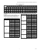
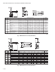
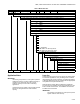


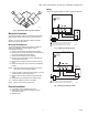
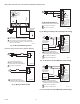


Table Of Contents

VBN2, VBN3 CONTROL BALL VALVES WITH THREADED CONNECTIONS
11 62-2648
Fig. 17. Wiring for Proportioning Controllers
(Modulating mode setting)
Fig. 18. Wiring for Proportioning controllers operating
multiple actuators (Modulating mode setting)
Fig. 19. Valve assembly exploded view.
NOTE: All identified parts except for the valve body and
aluminum valve stem coupler are included in
Replacement Kit (part no. 5112-11)
OPERATION AND CHECKOUT
Once both the mechanical and electrical installations are
complete:
1. Cycle the actuator to verify that the direction of rotation
suits the control sequence.
2. If the rotation direction is incorrect:
a. For 2-position control actuators: Remount actuator
on the bracket.
b. For floating control actuators: Reverse two control
signal wires (CW/CCW).
c. For analog control actuators either:
(1) Reposition reverse/direct acting switch, or
(2) Remount actuator on the bracket.
3. If the control scheme requires fail-safe operation, ensure
that, upon removal of power, the fail position coincides
with the control sequence.
4. If the fail safe position is incorrect, remove and reinstall
the actuator in the opposite orientation as follows:
ACTUATOR
0/2 TO 10 VDC
PROPORTIONING
CONTROLLER
24 VAC
1
1
2
3
2
LINE VOLTAGE POWER SUPPLY.
PROVIDE DISCONNECT MEANS AND
OVERLOAD PROTECTION AS REQUIRED.
24 VDC SUPPLY ACCEPTABLE.
SET SWITCH TO MODULATING.
V
OR +
OR N/A
FEEDBACK
–
+
FEEDBACK
5
4
3
1
2
M19574A
2-10 VDC
10-2 VDC
0-10 VDC
10-0 VDC
Fltg, fwd
Fltg, rev
3
ACTUATOR
4 TO 20 mA
PROPORTIONING
CONTROLLER
24 VAC
1
1
2
3
2
490 TO 510
OHMS,
1/2 W
MINIMUM
LINE VOLTAGE POWER SUPPLY.
PROVIDE DISCONNECT MEANS AND
OVERLOAD PROTECTION AS REQUIRED.
24 VDC SUPPLY ACCEPTABLE.
SET SWITCH TO MODULATING.
V
OR +
OR N/A
FEEDBACK
–
+
FEEDBACK
5
4
3
1
2
M22282A
2-10 VDC
10-2 VDC
0-10 VDC
10-0 VDC
Fltg, fwd
Fltg, rev
3
ACTUATOR
0/2 TO 10 VDC
PROPORTIONING
CONTROLLER
1
2
3
2
LINE VOLTAGE POWER SUPPLY.
PROVIDE DISCONNECT MEANS AND
OVERLOAD PROTECTION AS REQUIRED.
24 VDC SUPPLY ACCEPTABLE.
SET SWITCH TO MODULATING.
V
OR +
OR N/A
FEEDBACK
5
4
3
1
2
M22288
2-10 VDC
10-2 VDC
0-10 VDC
10-0 VDC
Fltg, fwd
Fltg, rev
3
ACTUATOR
V
OR +
OR N/A
FEEDBACK
5
4
3
1
2
2-10 VDC
10-2 VDC
0-10 VDC
10-0 VDC
Fltg, fwd
Fltg, rev
3
24 VAC
1
24 VAC
1
2
24 VAC
1
HOT
COM
–
+
M13738
VALVE BODY
VALVE STEM COUPLER
WING NUT**
MOUNTING
PLATE**
ANTI-ROTATION
BRACKET**
BOLT**
STEM ASSEMBLY COVER**
SCREWS (2)**
HANDLE (REMOVABLE) FOR
MANUALLY ROTATING SHAFT**
STEM ASSEMBLY**
**INCLUDED IN REPLACEMENT KIT (PART NO. 5112-11)
SCREWS (2)**