
Product Overview

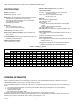
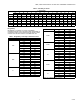
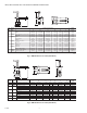
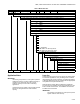


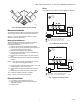
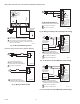
Table Of Contents

VBN2, VBN3 CONTROL BALL VALVES WITH THREADED CONNECTIONS
9 62-2648
Fig. 9. Acceptable valve angle from vertical
Mechanical Installation
The valves are tapped in NPT and should be sealed with an
approved pipe sealant. Torque should not exceed 75 lb-ft.
See Fig. 1 and 2 for valve dimensions. Refer to actuator
literature for actuator dimensions.
Mounting Plate Adjustment
The Actuator Mounting Plate can be rotated to a different
position for installation in confined spaces. This is
accomplished as follows:
1. Remove the handle from the shaft and set it aside.
2. Remove the two screws that hold the stem assembly to
the mounting plate and set them aside.
3. Remove and set aside the stem assembly.
4. Remove and set aside the two screws that attach the
mounting plate to the valve.
5. Remove and set aside hold-down ring from mounting
plate.
6. Rotate mounting plate around valve top to the desired
position.
NOTE: Take note of the screw hole positions on the valve.
They limit the mounting plate positions.
7. Lower ring down to valve body and engage it in the new
position relative to the mounting plate.
8. Tighten screws to valve body securing the mounting
plate.
9. Reattach the stem assembly to the mounting plate.
10. If desired, replace the handle on the shaft.
NOTE: See Fig. 19 for valve exploded view.
Electrical Installation
1. If necessary, remove actuator wiring cover.
2. Wire actuator using Figures 10 through 18 for the
application required.
3. Replace cover.
Wiring
Valves with Non-Spring Return Actuators (MN6105, MN7505)
Fig. 10. Wiring for On/Off Control
Fig. 11. Wiring for Floating Control
45 45
M19526
432
FLOATING ACTUATOR
24 VAC
1
1
POWER SUPPLY. PROVIDE DISCONNECT MEANS
AND OVERLOAD PROTECTION AS REQUIRED.
CONNECTION REQUIRED FOR SPST CONTROL.
2
CONTROLLER
2
Direct
Reverse
Service/Off
M18945A
4
3
2
FLOATING ACTUATOR
24 VAC
Direct
Reverse
Service/Off
1
1
POWER SUPPLY. PROVIDE DISCONNECT MEANS
AND OVERLOAD PROTECTION AS REQUIRED.
FLOATING
CONTROLLER
M18946A