
Product Overview
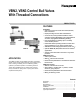


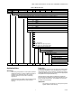


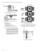
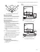
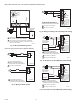
Table Of Contents

VBN2, VBN3 CONTROL BALL VALVES WITH THREADED CONNECTIONS
62-2648 8
Fig. 5. Boiler bypass for reset control.
Fig. 6. Supply mixing for reset control.
5. Stem rotation:
a. For two-way valves:
(1) Clockwise to close.
(2) Counterclockwise to open.
b. For three-way valves:
(1) Clockwise to increase B to AB flow.
(2) Counter clockwise to increase A to AB flow.
NOTE: After valves have been installed in the piping,
the installer can determine the ball orientation
within the valve from the notches in the top of
the valve stem. For two-way valves, the length-
wise direction of the notch indicates the flow
through the ball (i.e. when the notch is parallel
to the axis of the valve between A and B ports,
the ball will allow flow through the valve). For
three-way valves, the flow can be determined
by the orientation of the “T” shaped notch in the
valve stem, as shown in Fig. 7.
Fig. 7. Orientation of ball in valve
6. Valve must be mounted with the actuator/bracket above
the valve body. Do not install the valve with the stem
below horizontal or upside down. (See Fig. 7 and 8.)
Fig. 8. Vertical valve installation
AB A
B
M13736
BOILER
PUMP
VB3
MIXED
DISCHARGE
WATER TO
HEAT LOAD
BYPASS
AB
AB
M13735
BOILER
PUMP
VB3
A
AB
“T” POSITION ON TOP OF
3 WAY BALL VALVE STEM
B
AB
A
AB
M23450
B
A
AB
FULL FLOW
(ONLY FOR
2-WAY BODIES)
B
AB
B
AB
A
STEM
FULL FLOW
A AND B MIXED
TO AB,OR
A AND B DIVERTED
FROM AB, DEPENDING ON FLOW DIRECTION.
M19525