
Product Overview
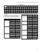
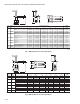
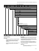


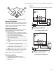
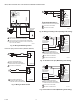


Table Of Contents

Automation and Control Solutions
Honeywell International Inc. Honeywell Limited-Honeywell Limitée
1985 Douglas Drive North 35 Dynamic Drive
Golden Valley, MN 55422 Toronto, Ontario M1V 4Z9
customer.honeywell.com
VBN2, VBN3 CONTROL BALL VALVES WITH THREADED CONNECTIONS
® U.S. Registered Trademark
© 2006 Honeywell International Inc.
62-2648 C.H. 08-06
a. Loosen the shaft coupling bolt using a 10 mm
wrench.
b. Loosen all other mounting bolts connecting the
actuator to the mounting bracket, and set aside.
c. Remove the actuator from the valve shaft.
d. Move the actuator coupling to the opposite side of
the actuator, as displayed in Figure 20.
Fig. 20. Mounting shaft coupling to actuator opposite side.
(1) Remove the retainer clip from the shaft coupling
and set it aside for later use.
(2) Remove shaft coupling from one side of the actu-
ator.
(3) Replace the shaft coupling on the opposite side
of the actuator, aligning it based on the stroke
labelling.
(4) Replace the retainer clip on the shaft coupling
using the groove of the coupling.
e. Reconnect the actuator to the valve mounting
bracket by replacing the screws previously removed
(step b)
f. Tighten the shaft coupling bolt using a 10 mm
wrench.
For detailed actuator information, see Honeywell literature:
• 63-2607—MS7505/MS8105 Actuator Product Data
• 63-2632—MN6105/MN7505 Floating Actuator Product Data
• 63-2633—MN6105/MN7505 Modulating Actuator Product
Data
TYPICAL SPECIFICATIONS
Ball Valve
Valve housing shall consist of forged brass rated at no less
than 360 psi at 250°F. Standard valve ball shall consist of
chemically nickel-plated brass. Manufacturer shall be able to
provide optional 316 stainless steel ball and stem for two-way
valves. Valve shall have a blow-out proof stem with two EPDM
O-rings with minimum 600 psi rating. Manufacturer shall be
able to provide glass-filled polymer ball insert to make flow
control equal percentage. Valves shall be Honeywell. Two-way
valves shall have EPDM O-rings behind ball seals to allow for a
minimum close-off pressure of 100 psi with actuator which
provides 35 lb-in. torque for 1/2 to 3 inches sizes. Valve shall
be available with a minimum of 53 unique C
V
values. Valve
shall be available with threaded (FNPT) end connections.
Three-way valves shall be installed in a “T” configuration with
actuator perpendicular to shaft. Valve shall not require elbows
of any kind. Three-way valves shall have EPDM O-rings
behind ball seals to allow for a minimum close-off pressure of
40 psi with an actuator that provides 35 lb-in. torque for 1/2 to
2-1/2 inches sizes. Three-way valves must be available in both
mixing and diverting configurations and shall be available with
a minimum of 42 unique C
V
values. Valve shall be available
with threaded (FNPT) end connections.
Valve Actuator
Control valve actuator shall accept analog modulating
[(0)2-10 Vdc], floating (tri-state), or two-position signal as
indicated in the control sequence. Actuators shall be by
Honeywell. Actuator shall provide minimum torque required for
full valve shutoff position. Wiring terminals shall be provided for
installation to control signal and power wiring.
Actuator shall be available with housing suitable for outdoor
installation.
Accessories Identification tags shall be available for all valves;
tags shall be indelibly marked with C
V
, model number, and tag
location.
M19579A