
Install Instructions


MVN 3Nm (27 lb-in.) Control Ball Valve Actuator
62-2025EFS—03 2
INSTALLATION
When installing this product...
1. Read these instructions carefully. Failure to follow them
could damage the product or cause a hazardous condi-
tion.
2. Check ratings given in instructions and on the product to
ensure the product is suitable for your application.
3. Installer must be a trained, experienced service techni-
cian.
4. After installation is complete, check out product opera-
tion as provided in these instructions.
Preparation
CAUTION
Equipment Damage Hazard
Foreign particles like dirt and metal chips can damage
the ball seals.
For trouble-free operation of the product, good
installation practice must include initial system
flushing, and chemical water treatment. Clean the
lines upstream of particles larger than 1/16 inch
diameter (welding slag, pipe scale, sand and other
suspended particulate). Use of a 50 micron (or finer)
system side stream filter is suggested. Remove all
filters before flushing.
Do not use boiler additives, solder flux and wetted
materials which are petroleum based or contain
mineral oil, hydrocarbons, or ethylene glycol acetate.
Compounds which can be used, with minimum 50%
water dilution, are diethylene glycol, ethylene glycol,
and propylene glycol (antifreeze solutions).
If installing these valves in an addition to, or retrofitting
an existing building, do not assume that the fluid in the
existing piping meets these criteria.
Mechanical Installation
IMPORTANT:
Hold valve with pipe wrench by hexagonal fitting
ONLY. Do NOT handle the valve body with the pipe
wrench; product damage may result.
The valves are tapped in NPT and should be sealed with an
approved pipe sealant. Torque should not exceed 75 lb-ft.
Refer to actuator literature for actuator dimensions.
1. Clean the lines upstream of particles larger than
1/16 in. diameter (welding slag, pipe scale and other
contaminants).
2. Proceed with installation once the system specifics
(expansion/contraction of the system and its medium as
well as operating pressures) are within tolerances.
3. Eliminate air from system.
4. Two-way valves are marked to show flow direction.
IMPORTANT
Flow arrows must point in the direction of the flow for
proper operation.
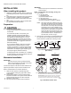
NOTE: For three-way valve mounting, see Fig. 1 & 2.
5. Stem rotation:
a. For two-way valves:
(1) Clockwise to close.
(2) Counterclockwise to open.
b. For three-way valves:
(1) Clockwise to increase B to AB flow.
(2) Counter clockwise to increase A to AB flow.
NOTE: After valves have been installed in the piping,
the installer can determine the ball orientation
within the valve from the notches in the top of
the valve stem. For two-way valves, the length-
wise direction of the notch indicates the flow
through the ball (i.e. when the notch is parallel
to the axis of the valve between A and B ports,
the ball will allow flow through the valve). For
three-way valves, the flow can be determined
by the orientation of the “T” shaped notch in
the valve stem, as shown in Fig. 2.
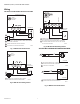
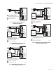
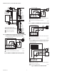
6. Valve must be mounted with the actuator/bracket above
the valve body. Do not install the valve with the stem
below horizontal or upside down. (See Fig. 4 and 6.)
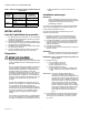
Fig. 1. Three-way ball valve flow orientation
(not to scale).
Fig. 2. Orientation of ball in valve.
M13737
SUPPLY
RETURN
AB PORT A PORT
B PORT
COIL
SUPPLY
RETURN
AB PORT A PORT
B PORT
COIL
MIXINGDIVERTING
M33201D
FLOW FLOW
2-WAY; CLOSED
3-WAY; B-AB OPEN
2-WAY; OPEN
3-WAY; A-AB OPEN
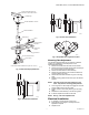
NOTES: FOR 2-WAY VALVES TO MOUNT ACTUATOR ON OPEN VALVE, TURN ACTUATOR
FULLY COUNTER CLOCKWISE AS SHOWN. FOR 2-WAY VALVES TO MOUNT
ACTUATOR ON CLOSED VALVE, TURN ACTUATOR FULLY CLOCKWISE AS SHOWN.
FOR 3-WAY VALVES TO MOUNT ACTUATOR ON A-AB VALVE, TURN ACTUATOR
FULLY COUNTER CLOCKWISE AS SHOWN. FOR 3-WAY VALVES TO MOUNT
ACTUATOR ON B-AB VALVE, TURN ACTUATOR FULLY CLOCKWISE AS SHOWN.