
Install Instructions


MVN 3Nm (27 lb-in.) Control Ball Valve Actuator
7 62-2025EFS—03
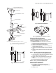
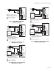
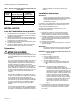
Fig. 20. MVN713 with 0 (2)-10 VDC Control.
NOTE: All identified parts except for the valve body and
aluminum valve stem coupler are included in
Replacement Kit (part no. 5112-11).
OPERATION AND CHECKOUT
Once both the mechanical and electrical installations are
complete:
1. Cycle the actuator to verify that the direction of rotation
suits the control sequence.
2. If the rotation direction is incorrect:
a. For 2-position control actuators: Remount actuator
on the bracket.
b. For floating control actuators: Reverse two control
signal wires (CW/CCW).
c. For analog control actuators either:
(1) Reposition reverse/direct acting switch, or
(2) Remount actuator on the bracket.
d. For modulating control actuators, reposition reverse/
direct acting switch 1.
3. If the control scheme requires fail-safe operation,
ensure that, upon removal of power, the fail position
coincides with the control sequence.
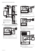
4. If the fail safe position is incorrect, remove and reinstall
the actuator in the opposite orientation as follows:
a. Loosen the shaft coupling bolt using a 10 mm
wrench.
b. Loosen all other mounting bolts connecting the
actuator to the mounting bracket, and set aside.
c. Remove the actuator from the valve shaft.
d. Move the actuator coupling to the opposite side of
the actuator, as displayed in Fig. 21.
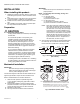
(1) Remove the retainer clip from the shaft coupling
and set it aside for later use.
(2) Remove shaft coupling from one side of the
actuator.
(3) Replace the shaft coupling on the opposite side
of the actuator, aligning it based on the stroke
labelling.
(4) Replace the retainer clip on the shaft coupling
using the groove of the coupling.
e. Reconnect the actuator to the valve mounting
bracket by replacing the screws previously removed
(step b)
f. Tighten the shaft coupling bolt using a 10 mm
wrench.
Fig. 21. Mounting shaft coupling to actuator
opposite side.
PROPORTIONAL ACTUATOR
24 VAC
1
POWER SUPPLY. PROVIDE DISCONNECT MEANS AND OVERLOAD
PROTECTION AS REQUIRED.
24 VDC SUPPLY ACCEPTABLE.
0 (2)-10 VDC
CONTROLLER
M33140A
1
2
3
+
+
–
DIP SWITCH POSITION
1 2 MODE
OFF OFF 2-10V
OFF ON 0-10V
ON OFF 10-2V
ON ON 10-0V
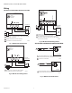
PROPORTIONAL/MODULATING: 0(2)...10 VDC OR 10...0(2) VDC CONTROLLER OUTPUT
2
RED
BLACK
WHITE
2
1
M19579A