
Install Instructions


MVN 3Nm (27 lb-in.) Control Ball Valve Actuator
3 62-2025EFS—03
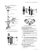
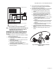
Fig. 3. Valve assembly exploded view.
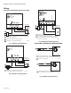
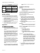
Fig. 4. Vertical valve installation.
Fig. 5. Vertical valve installation.
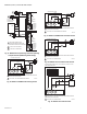
Fig. 6. Acceptable valve angle from vertical.
Mounting Plate Adjustment
The Actuator Mounting Plate can be rotated to a different
position for installation in confined spaces. This is
accomplished as follows:
1. Remove the handle from the shaft and set it aside.
2. Remove the two screws that hold the stem assembly to
the mounting plate and set them aside.
3. Remove and set aside the stem assembly.
4. Remove and set aside the two screws that attach the
mounting plate to the valve.
5. Remove and set aside hold-down ring from mounting
plate.
6. Rotate mounting plate around valve top to the desired
position.
NOTE: Take note of the screw hole positions on the
valve. They limit the mounting plate positions.
7. Lower ring down to valve body and engage it in the new
position relative to the mounting plate.
8. Tighten screws to valve body securing the mounting
plate.
9. Reattach the stem assembly to the mounting plate.
10. If desired, replace the handle on the shaft.
NOTE: See Fig. 3 for valve exploded view.
Electrical Installation
1. If necessary, remove actuator wiring cover.
2. Wire actuator using Figures 7 through 20 for the
application required.
3. Replace cover.
M13738
VALVE BODY
VALVE STEM COUPLER
WING NUT**
MOUNTING
PLATE**
ANTI-ROTATION
BRACKET**
BOLT**
STEM ASSEMBLY COVER**
SCREWS (2)**
HANDLE (REMOVABLE) FOR
MANUALLY ROTATING SHAFT**
STEM ASSEMBLY**
**INCLUDED IN REPLACEMENT KIT (PART NO. 5112-11)
SCREWS (2)**
M19525
M34954
45
45
M33091