
Install Instructions

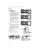

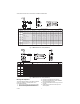


Table Of Contents

VBN2, VBN3 CONTROL BALL VALVES WITH THREADED CONNECTIONS
3 62-2009
5. Stem rotation:
a. For two-way valves:
(1) Clockwise to close.
(2) Counterclockwise to open.
b. For three-way valves:
(1) Clockwise to increase B to AB flow.
(2) Counter clockwise to increase A to AB flow.
NOTE: After valves have been installed in the pip-
ing, the installer can determine the ball ori-
entation within the valve from the notches
in the top of the valve stem. For two-way
valves, the lengthwise direction of the
notch indicates the flow through the ball
(i.e. when the notch is parallel to the axis
of the valve between A and B ports, the
ball will allow flow through the valve). For
three-way valves, the flow can be deter-
mined by the orientation of the “T” shaped
notch in the valve stem, as shown in
Fig. 5.
Fig. 5. Orientation of ball in valve
6. Valve must be mounted with the actuator/bracket
above the valve body. Do not install the valve with
the stem below horizontal or upside down. (See Fig.
6 and 7.)
Fig. 6. Vertical valve installation
Fig. 7. Acceptable valve angle from vertical
Mechanical Installation
The valves are tapped in NPT and should be sealed with
an approved pipe sealant. Torque should not exceed
75 lb-ft.
See Fig. 8 and 9 for valve dimensions. Refer to actuator
literature for actuator dimensions.
A
AB
“T” POSITION ON TOP OF
3 WAY BALL VALVE STEM
B
AB
A
AB
M23450
B
A
AB
FULL FLOW
(ONLY FOR
2-WAY BODIES)
B
AB
B
AB
A
STEM
FULL FLOW
A AND B MIXED
TO AB,OR
A AND B DIVERTED
FROM AB, DEPENDING ON FLOW DIRECTION.
M19525
45 45
M19526