
Install Instructions

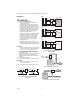

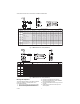


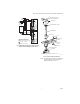

Table Of Contents

VBN2, VBN3 CONTROL BALL VALVES WITH THREADED CONNECTIONS
5 62-2009
NOTE: Take note of the screw hole positions on the
valve. They limit the mounting plate positions.
7. Lower ring down to valve body and engage it in the
new position relative to the mounting plate.
8. Tighten screws to valve body securing the mounting
plate.
9. Reattach the stem assembly to the mounting plate.
10. If desired, replace the handle on the shaft.
NOTE: See Fig. 19 for valve exploded view.
Electrical Installation
1. If necessary, remove actuator wiring cover.
2. Wire actuator using Figures 10 through 18 for the
application required.
3. Replace cover.
Wiring
VALVES WITH NON-SPRING RETURN ACTUATORS (MN6105,
MN7505)
Fig. 10. Wiring for On/Off Control
Fig. 11. Wiring for Floating Control
Fig. 12. Wiring for Modulating Control
432
FLOATING ACTUATOR
24 VAC
1
1
POWER SUPPLY. PROVIDE DISCONNECT MEANS
AND OVERLOAD PROTECTION AS REQUIRED.
CONNECTION REQUIRED FOR SPST CONTROL.
2
CONTROLLER
2
Direct
Reverse
Service/Off
M18945A
4
3
2
FLOATING ACTUATOR
24 VAC
Direct
Reverse
Service/Off
1
1
POWER SUPPLY. PROVIDE DISCONNECT MEANS
AND OVERLOAD PROTECTION AS REQUIRED.
FLOATING
CONTROLLER
M18946A
24 VAC
1
1
POWER SUPPLY. PROVIDE DISCONNECT MEANS
AND OVERLOAD PROTECTION AS REQUIRED.
PROPORTIONAL
CONTROLLER
+
-
FEEDBACK
1 32 5
PROPORTIONAL ACTUATOR
FEEDBACK
+
0(2)-10 VDC OF 0(4)-20 mA CONTROL SIGNAL ACCEPTABLE.
SET CONTROL SIGNAL DIP SWITCH TO "OFF" FOR VOLTAGE.
SET TO "ON" FOR CURRENT.
2
2
2 -10 Vdc
2 -10 Vdc
0 -10 Vdc
0 -10 Vdc
M18947A