
User's Manual


VC7900 SERIES MODULATING CONTROL VALVES
Automation and Control Solutions
Honeywell International Inc.
1985 Douglas Drive North
Golden Valley, MN 55422
customer.honeywell.com
® U.S. Registered Trademark
© 2011 Honeywell International Inc.
95C-10831—04 T.D. Rev. 02-11
Printed in U.S.A.
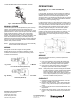
Fig. 6. Latch Mechanism to detach Actuator
MANUAL OPENER
The manual opener can be manipulated only when in the up
position. The motorized valve can be opened by firmly
pushing the white manual lever down to midway and in. In this
position both the “A” and “B” ports are open, and with auxiliary
switch models the switch is closed. This "manual open"
position may be used for filling, venting, or draining the
system, or for opening the valve in case of power failure. The
valve can be restored manually to the closed position by
depressing the white manual lever lightly and then pulling the
lever out. The valve and actuator will return to the automatic
position when power is restored.
NOTE: If the valve is powered open, it can not be manually
closed unless actuator is removed.
WIRING
See figures 7A and 7B for single unit wiring details.
Multiple valves may be connected in parallel to a single
controller and transformer, up to the current rating of the
controller and transformer.
Fig. 7a.Connector Pin Configuration for Molex™ Models
for 0-10 Vdc Controller (Series 70)
Fig. 7b. Wiring Colour Code for Cable Models for 0-10 Vdc
Controller (Series 70)
OPERATIONS
WITH SERIES 70, 0/2 - 10 VDC CONTROLLER
(refer to Fig. 7)
In the VC7900, an electronic circuit compares the voltage of
the feedback potentiometer to the signal voltage. If they are
different, then the circuit closes the appropriate triac and
drives the motor in the direction that will bring the circuit back
into balance. In addition, the standard limit switches maintain
the travel to the normal operating range.
In a direct acting model, 2 V signal will be fully closed, and 9 V
will be fully open. In a reverse acting model, 9 V is closed and
2 V is open. However, because of the soft close off of the VC
valve, initial (and final) movements of the actuator will not
cause any significant changes in the valve stem position.
On a loss of power, the actuator will remain in the last
position, and will resume normal operation on power up. On
loss of signal, a direct acting device will go to the closed
default position. A reverse acting device will go to the open
default position.
Fig. 8. Wiring Schematic of the VC7900 Series Actuator
SERVICE
This valve should be serviced by a trained, experienced
service technician.
1. If the valve is leaking, drain system OR isolate valve
from the system. Do not remove body from plumbing.
2. Check to see if the cartridge needs to be replaced.
3. If the motor or other internal parts of the actuator is
damaged, replace the entire actuator assembly.
NOTE: Honeywell hydronic valves are designed and tested
for silent operation in properly designed and installed
systems. However, water noises may occur as a
result of excessive water velocity. Piping noises may
occur in high temperature (over 212°F [100°C]) sys-
tems with insufficient water pressure.
CHECKOUT
1. Raise the set point of the thermostat above room tem-
perature to initiate a call for heat.
2. Observe all control devices - 2 way valve should open.
Port A in 3 way valve should open, and port B should
close.
3. Lower the set point of the zone thermostat below room
temperature.
4. Observe the control devices. 2 way valve should close.
Port A in 3 way valve should close, and port B should
open.
2