
Manual
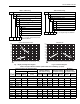

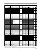
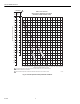


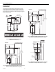
Table Of Contents

VGF FLANGED VALVES
63-2618 4
Fig. 3. Water capacity graph.
IMPORTANT
Valve sizing is important for correct system operation. Undersized valves do not have sufficient capacity at maximum
load. Oversized valves do not have sufficient authority over the load in modulating applications.
Oversized valves can initiate cycling and the seat and throttling plug can be damaged because of the restricted opening.
Some variables that must be determined are:
• Medium (steam, water, glycol solution 50 percent maximum) to be controlled.
• Maximum temperature and pressure of the medium at the valve.
• Pressure differential that exists across the valve under maximum load conditions.
• Maximum capacity the valve must deliver.
• Maximum line pressure differential against which the valve actuator must close.
Fig. 4. Dimensions for two-way models in inches (mm)
(See Table 6).
Fig. 5. Dimensions for three-way models in inches (mm)
(See Table 6).
M4908B
1
2
8
9
10
20
30
40
50
60
70
80
90
100
200
300
400
3
4
5
6
7
8
9
10
20
30
40
50
60
70
4000
900
800
700
600
500
400
300
200
100
90
80
70
60
50
40
30
20
3000
2000
1000
900
800
700
600
500
400
300
200
100
90
80
70
60
50
FLOW RATE (GPM)
FLOW RATE (m
3
/hr)
DIFFERENTIAL PRESSURE Dp (kPa)
DIFFERENTIAL PRESSURE Dp (psi)
6 IN. (150) C
V
= 400
5 IN. (125) C
V
= 250
4 IN. (100) C
V
= 160
3
IN. (
80) C
V
= 100
2
-1/2 IN. (
6
5) C
V
= 63
M22420
D
A
B
E
C
Stroke Y
1
DOTTED LINE REPRESENTS ANSI 125
VALVE BODY.
M22409
D
A
C
B
1
DOTTED LINE REPRESENTS ANSI 125
VALVE BONNET.
1
E
Stroke Y