
Manual
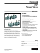

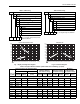
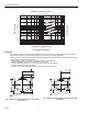
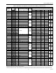


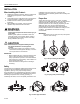


Table Of Contents

VGF FLANGED VALVES
9 63-2618
Fig. 11. Basic proper bolt length.
Location
Select a location where the valve and actuator are accessible.
Allow sufficient space for servicing the valve and actuator.
See Fig. 4 and 5 for valve body dimensions.
Fig. 12. Flanged valve body installation.
NOTE: See Table 1 for service flange part numbers.
Mounting the Valve
See Fig. 12 for typical installation.
1. Hoist valve by its body only. Do not lift by stem, bonnet,
flanges, or flange holes. (See Fig. 8.)
2. Install the valve so the flow follows the direction of the
arrow indicated on the valve body.
3. Install the valve so the actuator is above the valve body.
The valve can be installed in any position between verti-
cal and horizontal. Do not install the valve with the stem
below horizontal or upside down.
4. When controlling steam, use appropriate high
temperature kit 43196000 and rotate valve body so that
actuator is not positioned directly above the piping.
5. Use companion flanges with the same number of bolt
holes and dimensions as the valve to be installed. The
optional service flange may be installed in the lower
port. See Table 1 for part numbers. Use standard cast-
iron flanges for the two end ports.
6. Use a gasket material recommended for the medium to
be handled.
7. Use mounting bolts long enough so the nuts can use the
full length of the nut threads. (See Fig. 11.) Use bolts
1/8 in. smaller than the diameter of the bolt hole to allow
clearance for installing. (See Fig. 12.)
Mounting Actuator
For information on mounting, refer to the Product Data
literature for the actuator. Actuator installation clearances are
provided. It is important to have the correct actuator available
for the installation. See Table 7 for basic clearance
information.
Table 7. Installation Clearances (from Valve Bonnet, B).
133 IN-LB
(15 NM)
M22593
COMPANION
FLANGE
GASKET
GASKET
GASKET
BE SURE FACE OF COMPANION FLANGE IS FLUSH
WITH FACE OF VALVE-BODY FLANGE AND ALIGNED
SQUARELY BEFORE TIGHTENING MOUNTING NUTS.
OPTIONAL SERVICE FLANGE
COMPANION FLANGE
PIPE
M7977
Actuator
Minimum Vertical Clearance
in in. (mm)
ML6420, ML7420 12-11/16 (322)
ML6421A, ML7421A 14-1/4 (360)
ML6421B, ML7421B 16-7/8 (430)
ML6425A,B; ML7425A,B 14-5/16 (364)
MN/MS Series + Q5020 12 (305)
ML6984, ML7984
Modutrol IV + Q5001 14-1/2 (369)
MP953C (8 inch dia) 11-7/8 (302)
MP953C (13 inch dia) 17-11/16 (449)
MP953E (8 inch dia) 16-1/2 (420)
MP953E (13 inch dia) 25-13/16 (655)