
Install Instructions
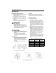
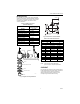

Table Of Contents

VGF FLANGED GLOBE VALVES
62-0213 2
INSTALLATION
When Installing this Product...
1. Read these instructions carefully. Failure to follow
them could damage the product or cause a
hazardous condition.
2. Check ratings given in instructions and on the
product to ensure the product is suitable for your
application.
3. Installer must be a trained, experienced service
technician.
4. After installation is complete, check out product
operation as provided in these instructions.
WARNING
Severe Burn Hazard.
Contact with hot liquid can lead to severe
injury or cause death.
Release system pressure and isolate or drain the
valve pipe section so the medium (steam, water
or glycol solution) does not leak out of the valve
body during installation (see Fig. 3).
CAUTION
Electrical Shock or Equipment Damage Hazard.
Can shock individuals or short equipment
circuitry.
Disconnect power supply to the actuator to
prevent electrical shock and equipment
damage, or remove and cap the air line to the
actuator.
IMPORTANT
• Before installing the valve, raise and lower the
valve stem to make sure that the valve stem
operates freely. Impaired stem operation can
indicate that the stem was bent by rough
handling. This condition can require replacing
the valve.
• Protect the stem from damage due to bending
or scratching.
Fig. 3. Piping must prevent leakage.
Location
Select a location where the valve and actuator are
accessible. Allow sufficient space for servicing the valve
and actuator. See Fig. 6 for valve body dimensions.
Mounting the Valve
See Fig. 5 for typical installation.
1. Hoist valve by its body only. Do not lift by stem,
bonnet, flanges, or flange holes. (See Fig. 1.)
2. Install the valve so the flow follows the direction of
the arrow indicated on the valve body.
3. Install the valve so the actuator is above the valve
body. The valve can be installed in any position
between vertical and horizontal. Do not install the
valve with the stem below horizontal or upside
down.
4. When controlling steam, use appropriate high
temperature kit 43196000 and rotate valve body so
that actuator is not positioned directly above the
piping.
5. Use companion flanges with the same number of
bolt holes and dimensions as the valve to be
installed. The optional service flange may be
installed in the lower port. See Table 1 for part
numbers. Use standard cast-iron flanges for the
two end ports.
6. Use a gasket material recommended for the
medium to be handled.
7. Use mounting bolts long enough so the nuts can
use the full length of the nut threads. (See Fig. 4.)
Use bolts 1/8 in. smaller than the diameter of the
bolt hole to allow clearance for installing. (See
Fig. 5.)
Table 1. Service Flange Part Numbers.
Fig. 4. Basic proper bolt length.
Valve Size
in in. (mm) ANSI 125 ANSI 250
2 1/2 (65) 208628 208633
3 (80) 208629 208634
4 (100) 208630 208635
5 (125) 208631 208636
6 (150) 208632 208637
133 in-lb
(15 Nm)