
Install Instructions
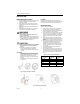
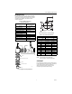
Table Of Contents

VGF FLANGED GLOBE VALVES
3 62-0213
Mounting Actuator
For information on mounting, refer to the Product Data
literature for the actuator. Actuator installation clearances
are provided. It is important to have the correct actuator
available for the installation. See Table 2 for basic
clearance information.
Table 2. Installation Clearances
(from Valve Bonnet, B).
Fig. 5. Flanged valve body installation.
Fig. 6. Dimensions for valve installation.
Table 3. Valve Sizes and Dimensions.
a
Three-way valves only.
NOTE: See VGF family Product Data sheet
(form 63-2618) for complete specifications.
CHECKOUT
For instructions for operating the valve actuator, see the
Product Data sheet for the specific actuator. Operate the
control system and check the valve operation to
determine that the valve stem positions the valve
smoothly through full stroke without binding.
Actuator
Minimum
Vertical Clearance
in in. (mm)
ML6420, ML7420 12-11/16 (322)
ML6421A, ML7421A 14-1/4 (360)
ML6421B, ML7421B 16-7/8 (430)
ML6425A,B; ML7425A,B 14-5/16 (364)
MN/MS Series + Q5020 12 (305)
ML6984, ML7984
Modutrol IV + Q5001 14-1/2 (369)
MP953C (8 inch dia) 11-7/8 (302)
MP953C (13 inch dia) 17-11/16 (449)
MP953E (8 inch dia) 16-1/2 (420)
MP953E (13 inch dia) 25-13/16 (655)
COMPANION
FLANGE
GASKET
GASKET
GASKET
BE SURE FACE OF COMPANION FLANGE IS FLUSH
WITH FACE OF VALVE-BODY FLANGE AND ALIGNED
SQUARELY BEFORE TIGHTENING MOUNTING NUTS.
OPTIONAL SERVICE FLANGE
COMPANION FLANGE
PIPE
M7977
Size
Dimensions, in. (mm)
See Fig. 6
in. DN A D
a
ANSI Class 125
2-1/2 65 10-7/8 (276) 3-3/4 (95)
3 80 11-3/4 (298) 4-3/8 (111)
4 100 13-7/8 (352) 5-1/8 (130)
5 125 15-3/4 (400) 5-3/4 (146)
6 150 17-3/4 (451) 6-5/8 (168)
ANSI Class 250
2-1/2 65 11-1/2 (292) 3-3/4 (95)
3 80 12-1/2 (318) 4-3/8 (111)
4 100 14-1/2 (368) 5-1/8 (130)
5 125 16-5/8 (422) 5-3/4 (146)
6 150 18-5/8 (473) 6-5/8 (168)
M22409
D
A
C
B
1
DOTTED LINE REPRESENTS ANSI 125
VALVE BONNET.
1
E
Stroke Y