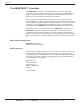
SMARTBOX™ CONTROLLER for HONEYWELL™ Wind Turbine Model WT6500 Owner’s Manual This manual is intended for the use of a licensed contractor. If you are a licensed and insured contractor who would like to become an Authorized Installer, please send your request to Installer@WindTronics.com. The HONEYWELL™ trademark is used under license from Honeywell International Inc. Honeywell International Inc. makes no representations, or warranties with respect to this product or service.
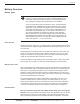
Safety Instructions II Safety Instructions PLEASE READ THESE INSTRUCTIONS AND THE ENTIRE MANUAL PRIOR TO INSTALLATION. Safety Icons The following symbols identify dangers associated with the installation, use or ownership of the SMARTBOX™ Controller. When you see these symbols, please be aware of the potential for personal injury or property damage. WARNING indicates a hazard that could result in death, personal injury or property damage. CAUTION indicates a hazard that could result in property damage.
Safety Instructions III LIMITATIONS ON USE The SMARTBOX™ Controller is not intended for use in connection with life support systems or other medical equipment or devices. Battery Safety Information A battery can produce the following hazards to personal safety: • electrical shock • burn from high-short-circuit current • fire or explosion from vented gasses Observe proper precautions when working with or around batteries.
Safety Instructions IV The SMARTBOX™ Controller for the HONEYWELL™ Wind Turbine WT6500 is manufactured by WindTronics Inc. Please contact WindTronics Inc. at: 621 Sprucewood Avenue Windsor, Ontario N9C 0B3 877-946-3898 The Honeywell Trademark is used under license from Honeywell International Inc. Honeywell International Inc. makes no representations or warranties with respect to this product.
Safety Instructions V SMARTBOX™ Controller for HONEYWELL™ Wind Turbine WT6500 Owner’s Manual - Rev14
Table of Contents VI Table of Contents Safety Instructions....................................................... II 1. Introduction The SMARTBOX™ Controller................................................... 2 Major System Components.................................................... 2 Parts Inspection................................................................... 2 Battery Overview..................................................................... 3 Battery Types..............................
Table of Contents VII 3. Commisioning Commissioning Process......................................................... 24 4. Operation Introduction............................................................................. 28 Turbine Operating States....................................................... 28 Starting/Stopping Turbine....................................................... 28 Viewing Operating Status.......................................................
Introduction 1 1 Introduction Chapter 1 describes the SMARTBOX™ Controller with battery overview and selection details.
Introduction 2 The SMARTBOX™ Controller The SMARTBOX™ Controller is a proprietary WindTronics control system that consists of a charge controller and a non-grid-tie 1.5 kW inverter. Included within the charge controller is an automatic AC transfer switch that will automatically switch between your AC grid and power generated via the turbine. The DC output from the turbine is fed into the Junction Box located beneath the turbine assembly.
Introduction 3 Battery Overview Battery Types Batteries are classified in two different ways: by application (their use) and construction (how they are built). The major applications are automotive, marine and deep cycle. Deep cycle includes solar electric (PV), wind power, backup power and RV/boat “house” batteries. The major construction types are flooded (or “wet”), gel and AGM (Absorbed Glass Mat).
Introduction 4 The popular golf cart battery is generally a “semi” deep cycle - better than any starting battery, better than most marine, but not as good as a true deep cycle solid lead plate, such the L-16 or industrial type. Amp-hour Ratings All deep cycle batteries are rated in amp-hours. An amp-hour (Ah) is a unit of electric charge measurement, calculated by multiplying amps by hours.
Introduction 5 • • • Water pumps can be add to the panel, but the pump must be rated at 120 VAC. Typically, 1500W can handle all the lighting and some appliances. You may want to mark wall plugs in the home to indicate that the plug is on wind turbine power instead of grid power.
Introduction 6 • Refrigerator (frost-free, 16 cubic feet) = 725 • Toaster = 800–1400 • Toaster oven = 1225 • Vacuum cleaner = 1000–1440 • Water heater (40 gallon) = 4500–5500 • Water bed (with heater, no cover) = 120–380 SMARTBOX™ Controller for HONEYWELL™ Wind Turbine WT6500 Owner’s Manual - Rev14
SMARTBOX Installation 7 2 SMARTBOX™ Controller Installation Chapter 2 provides details on installing the SMARTBOX™ Controller and getting it ready for operation.
SMARTBOX Installation 8 System Diagrams TIP: The instructions in this section apply to a typical installation. Installation procedures may vary according to your specific application. For special applications, consult a qualified electrician or your WindTronics certified dealer. PROFESSIONAL INSTALLATION: Installation must be compliant with all local electrical codes. Installation of this equipment should only be performed by a qualified electrician or by a Certified Renewable Energy System Installer.
SMARTBOX Installation 9 SMARTBOX™ Controller Diagram CHARGER DSP CONTROL INVERTER OVP CHARGE CONTOL AC TRANSFER SWITCH IO BOARD CURRENT/ VOLTAGE SENSING CURRENT/ VOLTAGE SENSING CURRENT/ VOLTAGE SENSING CURRENT/ VOLTAGE SENSING SYSTEM POWER DC GFI ISOLATED LOGIC CONTROL EQUIPMENT GROUND WIND TURBINE HV POWER INPUT 24V BATTERY BANK TURBINE LOGIC CONTROL RS485 AC OUT AC GRID FROM TURBINE Figure 2.
SMARTBOX Installation 10 Minimum Clearance for Proper Mounting allow for at least 150 mm (6 in) clearance. allow for at least 300 mm (12 in) clearance. allow for at least 300 mm (12 in) clearance. allow for at least 508 mm (20 in) clearance. allow for at least 150 mm (6 in) clearance. Figure 2.3 Minimum Clearance for Proper Mounting EQUIPMENT DAMAGE Never install the SMARTBOX™ Controller where it is exposed to salt water spray.
SMARTBOX Installation 11 Grounding The SMARTBOX™ Controller is designed to work only with the HONEYWELL™ Wind Turbine. The turbine uses a negative-grounded electrical system. Grounding for the turbine, battery and AC circuits are provided inside the wiring compartment. Each ground connection can accommodate up to #6 AWG wire size. GFI: A fuse rated at .5A 250V, accessible from the bottom of the wiring compartment, grounds the negative conductor of the turbine and provides turbine ground-fault protection.
GRN/WHT SEE TURBINE TO CONTROLLER SIZE CHART ON SHEET 1 GRN (2) #10 THWN-2 + #6 GND ¾” CONDUIT MAX DISTANCE 3 FEET. Figure 2.4 12V 12V 12V SMARTBOX™ Controller for HONEYWELL™ Wind Turbine WT6500 Owner’s Manual - Rev14 OPTIONAL 12V 12V BRN/WHT GRN GRN/WHT (2) #4 THWN-2 + #4 GND 1” CONDUIT MAX DISTANCE 6 FEET.
SMARTBOX Installation 13 Turbine Wiring and Distances The HONEYWELL™ Wind Turbine and SMARTBOX™ Controller can be installed at a maximum distance of 200 feet apart. The SMARTBOX™ Controller and battery enclosure can be installed at a maximum distance of 10 feet apart. Turbine Current Rating and Wiring The turbine input is rated for 20 amps maximum Isc (short circuit). The recommended wire type is #10 AWG USE-2/RHW-2 or THWN-2, 90 degrees C wire for a turbine-toSmart-Box distance of up to 150 feet.
SMARTBOX Installation 14 Turbine Over-current Protection The NEC requires the turbine circuit to be protected with a device rated for 125% of the rating of the circuit. The DC-rated fuse or circuit breaker between the turbine and the SMARTBOX™ Controller must have a maximum size of 15 (the maximum current rating of the SMARTBOX™ Controller).
SMARTBOX Installation 15 Battery Wiring The battery charge current is rated at 60 amps and inverter current is rated 72 amps maximum. The recommended wire type is #4 AWG USE-2/RHW-2 or THWN-2, 90 degrees C wire for a SMARTBOX™ Controller-to-battery-enclosure distance of up to 6.3 feet. The wire gauge should be increased to #2 AWG wire for a distance of 6.3-10 feet. Figure 2.
SMARTBOX Installation 16 Battery Over-current Protection The NEC/CEC requires the battery circuit to be protected with a device rated for 125% of the rating of the circuit. The DC-rated fuse or circuit breaker between the battery and the SMARTBOX™ Controller must have a maximum size of 75A (the maximum current rating of the SMARTBOX™ Controller).
SMARTBOX Installation 17 AC Input Wiring The AC input current is rated at 15 amps. Use standard NEC calculations and local codes for proper wiring. Figure 2.9 AC Output Wiring AC Input Current Wiring Diagram The AC output current is rated at 15 amps. Use standard NEC calculations and local codes for proper wiring. Figure 2.
SMARTBOX Installation 18 AC Output Over-current Protection The NEC/CEC requires the AC output circuit to be protected with a device rated for 125% of the rating of the circuit. The AC-rated fuse or circuit breaker between the battery and the SMARTBOX™ Controller must have a maximum size of 15A (the maximum current rating of the SMARTBOX™ Controller).
SMARTBOX Installation 19 Control Wiring CAT5E or CAT6 Control wiring can use stranded CAT5, CAT6 or equivalent wire. ORG ORG/WHT BLU BLU/WHT BRN/WHT GRN ORG ORG/WHT BLU BLU/WHT BRN BRN/WHT GRN Figure 2.
SMARTBOX Installation 20 Enclosure Internal Wiring NEC/CEC and UL require that no wires cross within the Junction Box. Punch outs have been provided on the bottom of the Junction Box to meet this requirement. Battery Setup FIRE HAZARD Batteries must be set correctly to avoid explosion or fire. Failure to follow this warning may result in death, personal injury or property damage.
SMARTBOX Installation 21 To connect the SMARTBOX™ Controller: 1. Mount SMARTBOX™ Controller to the wall per instructions on pages 9-10; Figure 2.3. 2. Place battery enclosure in a dry, well-ventilated indoor space. 3. Install and level turbine. See the HONEYWELL™ WindTurbine Owner’s Manual. SHOCK HAZARD Always lock the blades before working with the turbine. Unlocked blades can produce voltages on the DC output. Failure to follow this warning may result in death, personal injury or property damage. 4.
SMARTBOX Installation SMARTBOX™ Controller for HONEYWELL™ Wind Turbine WT6500 Owner’s Manual - Rev14 22
Commissioning 23 3 Commissioning Chapter 3 describes the step by step process of commissioning the SMARTBOX™ Controller.
Commissioning 24 Commissioning Process EXPLOSION OR FIRE HAZARD Entering battery information incorrectly may result in explosion or fire. During commissioning, the SMARTBOX™ Controller and turbine must be set up. Settings for the battery type, battery banks and battery capacity must be set up in the SMARTBOX™ Controller, and the turbine’s components will need to be tested. This testing can be done with the control panel and LCD screen on the front of the system controller.
Commissioning 25 6. Select the battery Amp-hour rating for ONE battery by using the arrow keys. Press ENTER when finished. Display Description Optimal ENTER BATTERY AHr 100 Set the battery amp-hour rating Enter 140 for 100Ahr for ONE battery batteries 7. Select the number of battery banks in parallel by using the arrow keys. Press ENTER when finished. Display Description Optimal ENTER BATTERY BANKS 1 Set the number of battery banks Enter 3 for one bank of 2-12V batteries 8.
Commissioning 26 SMARTBOX™ Controller for HONEYWELL™ Wind Turbine WT6500 Owner’s Manual - Rev14
Operation 27 4 Operation Chapter 4 is an overview of SMARTBOX™ Controller operation including operating states, system faults and menu structures.
Operation 28 Introduction The basic operation of the turbine/SMARTBOX™ Controller electronic system is to optimize the efficient utilization of the energy captured from the wind. Low wind energy is stored in batteries while loads are connected automatically to the grid. High wind energy is efficiently and rapidly transferred to the load via the bulk storage capacity of the batteries.
Operation 29 Controller Energy Consumption States • Display On State The Display state is enabled by pressing any key on the SMARTBOX™ Controller. This state will enable the LCD backlight and cause user information to scroll on the second line of the LCD screen. This state is also active when accessing the menus. If no buttons are pressed, the SMARTBOX™ Controller will automatically switch back to the running state.
Operation 30 the energy consumption state (see the Fault and Troubleshooting section for complete details): Display- Display State Description TURBINE FAULT GFI Turbine is stopped and contains a GFI fault. TURBINE FAULT NO WIND SPEED Voltage sensed but Anemometer not sensing wind speed. TURBINE FAULT TURBINE OVER CURRENT Turbine is stopped and contains an over current fault. TURBINE FAULT TURBINE OVER VOLTAGE Turbine is stopped and contains an over temperature fault.
Operation 31 System Faults The SMARTBOX™ Controller constantly monitors the status of the turbine. Any time the turbine senses a fault, the dynamic brake will stop the turbine and the SMARTBOX™ Controller will stop producing energy from the turbine. “TURBINE FAULT” will be displayed on the LCD screen along with the fault detected. The user must clear any faults in order to restart the turbine. If a fault occurs, follow these steps to clear it: 1. View the faults listed and correct the fault. 2.
Operation 32 SMARTBOX™ Controller Front Panel .TECHNICIAN ..BATTERY SETUP BACK Figure 4.4 UP DOWN ENTER SMARTBOX™ Controller Front Panel Navigation Buttons 1. BACK button. The back button will bring you back to the previous menu level and CANCEL any changes made. 2. UP button. The up button will scroll through the current menu selections or make a configuration change depending on the current menu level. 3. DOWN button.
Operation 33 1. This is the home screen. The SMARTBOX™ Controller will scroll the listed information while in run mode and also the current firmware revision. 2. Turbine Fault Stop. Indicates if a fault has occurred. 3. This is the top menu level. From here you can go to the TECHNICIAN MENU or the START/STOP TURBINE MENU. Pressing enter to make a selection. 4. The Start/Stop Turbine Menu. Pressing UP will place the SMARTBOX™ Controller in user stop mode.
Operation 34 View Data Menu 1 .VIEW-TURBINE INPUT V=100 I=4 P=400 UP/DWN 2 .VIEW-BATTERY CHARGE V=27.2 I=2 P=54.4 UP/DWN 3 .VIEW-INVERTER V=27.2 I=0 P=0 UP/DWN 4 UP/DWN .VIEW-AC OUTPUT V=120 I=0 P=0 UP/DWN 5 .VIEW-ENVIRONMENT ws=5 wd=16 UP/DWN 6 .VIEW-TEMPERATURE Te=30 Tc=35 Ti=0 UP/DWN 7 .VIEW-WS POWER ws=10 P=400 E=34 Figure 4.7 View Data Menu 1. Turbine Input. This screen shows the turbine output voltage (VDC), current (amps) and power (W). 2. Battery charge.
Operation 35 Battery Setup Menu RISK OF FIRE OR EXPLOSION These settings must be followed correctly. Setting them incorrectly will highly increase the risk of fire and/or battery explosion. Failure to follow this warning may result in death, personal injury or property damage. 1 ..BATTERY SETUP ...TYPE ? ENTER/BACK ..BATTERY SETUP Type=FLOODED ENTER/BACK ..BATTERY SETUP AHr=100 ENTER/BACK ..BATTERY SETUP Banks=1 ENTER/BACK ..BATTERY SETUP Voltage=23.0 ENTER/BACK ..
Operation 36 SMARTBOX™ Controller for HONEYWELL™ Wind Turbine WT6500 Owner’s Manual - Rev14
Specifications 37 5 Specifications SMARTBOX™ Controller for HONEYWELL™ Wind Turbine WT6500 Owner’s Manual - Rev14
Specifications 38 Non Grid-Tie Smart Box Electrical Specifications Description Rating Units Maximum Turbine Voltage 200 Volts DC Operating input voltage range 30-170 Volts DC Maximum input current 18 Amps DC Maximum input short circuit current 20 Amps DC Operating voltage range 120VAC+/-3% Volts AC Operating frequency range or single frequency 60Hz+/-0.05% Hz Nominal output voltage (ac) 120 Volts AC Nominal output frequency 60 Hz Maximum continuous output current 12.
The Honeywell Trademark is used under license from Honeywell International Inc.and makes no representations or warranties with respect to this product. WindTronics Honeywell International Inc. 621 Sprucewood Avenue Windsor, Ontario N9C 0B3 Tell: 877-946-3898 www.honeywell.