Page 2-8 and 8-1 Has been edited by Tech Support. If you have any questions call 1.800.645.7492 ADEMCO VISTA SERIES VISTA-20P / VISTA-20PSIA VISTA-15P / VISTA-15PSIA Security Systems Installation and Setup Guide K5305-1V5 10/04 Rev.
RECOMMENDATIONS FOR PROPER PROTECTION The Following Recommendations for the Location of Fire and Burglary Detection Devices Help Provide Proper Coverage for the Protected Premises. Recommendations For Smoke And Heat Detectors With regard to the number and placement of smoke/heat detectors, we subscribe to the recommendations contained in the National Fire Protection Association's (NFPA) Standard #72 noted below.
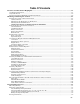
Table Of Contents Features and Installation Highlights............................................................................................................1-1 Capabilities and Functions................................................................................................................................................1-1 Compatible Devices .........................................................................................................................................................
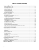
Table Of Contents (continued) Data Field Programming .................................................................................................................................4-1 About Data Field Programming........................................................................................................................................4-1 System Setup Fields (∗20 – ∗29) ..............................................................................................................................
S E C T I O N 1 Features and Installation Highlights This manual applies to the following Honeywell security systems: ADEMCO VISTA-20P/ADEMCO VISTA-20PSIA/ADEMCO VISTA-20PCN (collectively referred to as VISTA-20P series), ADEMCO VISTA-15P/ADEMCO VISTA-15PSIA/ADEMCO VISTA-15PCN (collectively referred to as VISTA-15P series) Features and procedures apply to all, except where differences are noted.
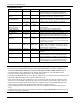
Installation and Setup Guide Compatible Devices Device Addressable Keypads VISTA-20P 8 VISTA-15P 8 2 2 Up to 5 for up to 40 exp. zones Up to 40 RF zones Up to 16 Up to 2 for up to 16 exp. zones Up to 26 RF zones Up to 8 2 Up to 48 Partition 1 only 2 Up to 24 yes Audio Alarm Verification Using AAV module Using AAV module Alarm output 12VDC, 2 AMP output 12VDC, 2 AMP output Auxiliary Power Output Backup Battery See note. See note. See note See note. Long Range Radio See note. See note.
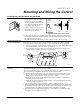
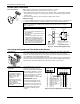
S E C T I O N 2 Mounting and Wiring the Control Installing the Control Cabinet and PC Board Mounting the PC Board Alone (no RF Receiver) LOCKED PUSH ON LOCK UNTIL IT IS SEATED SECURELY SNAP TAB PUSH UNLOCKED CABINET DOOR BOTTOM SNAP TAB STEP 1 STEP 2 cab_lock_snap-001-V0 2. Remove cabinet door, then remove the lock knockout from the door. Insert the key into the lock. CHECK POSITION ADEMCO 1.
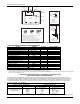
Installation and Setup Guide CABINET A B CABINET BOARD SUPPORTING SLOTS RECEIVER CIRCUIT BOARD + + CIRCUIT BOARD MOUNTING CLIP CONTROL CIRCUIT BOARD DETAIL A MOUNTING CLIP SIDE VIEW OF BOARD SUPPORTING SLOTS INSTALLATION WITH RECEIVER CIRCUIT BOARD ANTENNA (2) SCREW (2) GROUNDING LUG (2) WHITE MOUNTING CLIP BLACK MOUNTING CLIP RED MOUNTING CLIP NOTE A COMBINATION OF THESE MOUNTING CLIPS HAS BEEN INCLUDED IN YOUR INSTALLATION KIT. USE THE APPROPRIATE CLIPS FOR MOUNTING.
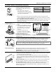
Mounting and Wiring the Control AC Power, Battery, and Ground Connections Connect the 1321 Transformer (1321CN in Canada) to terminals 1 and 2 on the control board. See Wire Run Chart for wire size to use. • Use caution when wiring the transformer to the control to guard against blowing the transformer fuse (the fuse is non-replaceable).
Installation and Setup Guide Sounder (Bell) Connections Basic Connections 4 Supervised output 1. Cut the red Bell Supervision Jumper located above terminals 2 and 3 on the PC board. 2. Connect a 2k ohm resistor across the terminals of the last sounder. See Figure 5. spkr_conn-001-V0 ALARM OUTPUT 10.5 - 13.5 VDC 2A MAX. This control complies with NFPA requirements for temporal pulse sounding of fire notification appliances.
Mounting and Wiring the Control Keypad Notes AR ME RE Set device addresses. Refer to the instructions included with the devices and set each address according to the Table of Devices Addresses. See Keypad Programming Fields (fields *190-*196) in Section 4. Data Field Programming for details on enabling keypad addresses, assigning keypad partitions and selecting keypad sounding options.
Installation and Setup Guide Hardwire Zones and Zone Expansion Hardwire Zones Normally Open Zones/ N.O. EOLR Zones 1. Connect open circuit devices in parallel across the loop; for EOLR zones, connect the EOLR across the loop wires at the last device. 2. Enable normally open/EOLR zones using Zone Programming mode, “Hardwire Type” prompt. LO zones-001-V0 HI Normally Closed Zones/ N.C. EOLR Zones 1.
Mounting and Wiring the Control Smoke Detector Notes • Fire Verification (zone type 16): The control panel will “verify” a fire alarm by resetting the smoke detectors after the first alarm trigger, and then waiting 90 seconds for a second alarm trigger. If the smoke detector or thermostat does not trigger again, the control will disregard the first trigger, and no alarm signal will occur. This feature eliminates false alarms due to electrical or physical transients.
Installation and Setup Guide RELAY CONNECTOR 4229 RELAY 2 DIP SWITCH FOR SETTING ADDRESS AND ZONE "A" RESPONSE EITHER OR BOTH CAN BE USED RELAY 1 TB2 4-PIN CONSOLE PLUG NO C NC GRY VIO BLK YEL ORG BRN 4229 REMOTE (TAMPER PROTECTED) NO NC C GND NO NC C WHT TAMPER JUMPER POSITION 4229 IN CABINET (NOT TAMPER) RLY 2 RLY 1 RELAYS OFF 2 1 3 4 TB1 6 5 8 7 9 10 11 A B C D E F G 4 3 4 3 2 12 2 1 1 GRN DATA OUT (>) TO CONTROL BLK (TERM 6) (–) GROUND (TERM 4) (+) 12VDC YEL DAT
Mounting and Wiring the Control Installing a 5800TM Module Installing the Transmitters • Use this module only if you are using one or more wireless bi-directional keypads or keyfobs with a wireless Receiver; 5800TM is not necessary if using a Transceiver (e.g., 5883). • The 5800TM must be set to address 28 (cut red-W1 jumper). • The 5800TM can be used in partition 1 only. • For additional information regarding the 5800TM, refer to the 5800TM’s instructions. 1.
Installation and Setup Guide Installing a Keyswitch Keyswitch Connections GREEN RED 1. Connect the 4146 keyswitch's normally open momentary switch to a zone’s (2-8) terminals. Remove the 2000 ohm EOL resistor if connected across the selected zone. 2. Using a standard keypad cable as shown: Connect the yellow and white keyswitch wires to trigger connector pin 3 (+12V). Connect the Red and Green LED wires to the appropriate output 17/output 18 trigger connector pins. 3.
Mounting and Wiring the Control Connecting Relay Modules, Powerline Carrier Devices and Output Triggers RELAY 4-PIN TOUCHPAD PLUG 2 13 14 15 NC NO C NC 16 YEL BLK GRN RED 4 NO NO RELAY C 1 NC 1 TB1 C NC 3 EITHER OR BOTH CAN BE USED 10 11 12 3 COVER TAMPER (REED) SWITCH For UL installation requirements, refer to the Installation Instructions for the 4204.
Installation and Setup Guide Connect field wiring to the desired trigger pin on the 8-pin trigger connector centrally located above the terminal strip. • If using 1361X10 transformer and powerline carrier devices, use the SA4120XM-1 cable (part of 4120TR Trigger Cable). See Wiring the AC Transformer section for transformer connections. • If only using the on-board triggers, you can use a 4-wire cable (N4632-4, supplied with the control) as shown below. 00-trigcon-003-V1 Figure 15a.
Mounting and Wiring the Control Phone Line/Phone Module, and Audio Alarm Verification (AAV) Connections Compatibility: 4286 Phone Modules must have software version WA428615.1 or higher (refer to the label on the square 4286 microprocessor chip). IMPORTANT NOTE FOR EXISTING INSTALLATIONS: EXISTING WIRES CONNECTED TO THE "HANDSET" TERMINALS ON CONTROL MUST BE MOVED FROM THERE TO TERMINALS 3 AND 4 ON THE 4285/4286. LOUDER 24 TO EARTH GROUND (COLD WATER PIPE, ETC.
Installation and Setup Guide Audio Alarm Verification Connections (AAV, “listen-In”) • Refer to the connection diagrams below. One diagram shows connections when a 4285/4286 Phone Module is used, the other shows connections when the 4285/4286 is not used. • Connections use one of the on-board triggers. • Set field *91 for AAV and program the appropriate output (output 17 or 18) using *80 Menu mode: select zone type 60 and output action 1 (close for 2 seconds) or action 2 (stay closed).
S E C T I O N 3 Programming Overview About Programming • You can program the system at any time, even at the installer's premises prior to the actual installation. • Programming can also be performed remotely from the installer’s office/home, using an IBM personal computer, a modem, and Compass downloading software. The following is a list of the various Programming modes used to program this system.
Installation and Setup Guide Interactive Mode Programming (∗ ∗56, *57, ∗58, ∗79, ∗80, ∗81, ∗82) Entering Interactive Mode Press [∗] + [Interactive Mode No.] (for example, ∗56) while in Program Mode. The Alpha display keypad will display the first of a series of prompts. After making the appropriate entry, press the [∗] key to accept the entry and continue to the next prompt. Loading Factory Defaults/Initializing for Download To Load Default Entries Press ∗97 while in Program Mode.
Programming Overview • Assign to a zone that contains a foil-protected door or window (such as in a store), or to a zone covering a sensitive area such as a stock room, drug supply room, etc. • Can also be used on a sensor or contact in an area where immediate notification of an entry is desired. • Provides an instant alarm if faulted when armed in the Away, Stay, Night-Stay, Instant or Maximum (night) modes.
Installation and Setup Guide Type 23 * No Alarm Response • Can be used on a zone when an output relay action is desired, but with no accompanying alarm (e.g., lobby door access). Type 24 Silent Burglary • Usually assigned to all sensors or contacts on exterior doors and windows where bells and/or sirens are NOT desired. • Provides an instant alarm, with NO audible indication at any keypad or external sounder, if the zone is faulted when the system is armed in the Away, Stay, Instant, or Maximum modes.
S E C T I O N 4 Data Field Programming About Data Field Programming The following pages list this control’s data fields in numerical order. Valid entries for each field are shown in italics. Explanations and special notes are presented below the entries. Use the separate Programming Guide to record the data for this installation. Data field programming involves making the appropriate entries for each of the data fields. Start Data Field programming by entering the installer code + 8 + 0 + 0.
Installation and Setup Guide *32 Fire Alarm Sounder Timeout *38 Confirmation Of Arming Ding 0 = yes; sounder timeout after time selected in field ∗33 1 = no timeout; sounds until manually turned off This control complies with NFPA requirements for temporal pulse sounding of fire notification appliances. Temporal pulse sounding for a fire alarm consists of the following: 3 pulses – pause – 3 pulses – pause – 3 pulses. UL fire alarm installations: must be 1.
Data Field Programming *47 Phone System Select *54 Dynamic Signaling Delay If Central Station Receiver is not on WATS line: 0 = Pulse Dial; 1 = Tone Dial If Central Station Receiver is on WATS line: 2 = Pulse Dial; 3 = Tone Dial Select the type of telephone service. 0 = disabled (both signals sent); 1–15 = entry times a 15-second delay. e.g., 1 = 15 seconds, 2 = 30 seconds, etc. Intended for use with Long Range Radio reporting.
Installation and Setup Guide System Status Report Codes *60 Trouble Report Code Zone report codes are programmed using interactive ✱56 or ✱58 Zone Programming modes, while system status (non-alarm) codes and restore codes are entered in data fields *59 - *68, *70 - *76, *89. The actual report code digits that you enter depend upon the particular installation, and should agree with the Central Station office receiving the signals.
Data Field Programming *69 Recent Closing Report V20PSIA/V15PSIA only Always enabled. Field does not apply to other controls. Similar to the Exit Error condition described in field *59, but occurs if an entry/exit door or interior zone is faulted within two minutes after the initial exit delay expires. Disarming the system within the two minutes stops the alarm sound and displays "ALARM CANCELED " or "CA" and the faulted zone number. No message is sent to the Central Monitoring Station.
Installation and Setup Guide *87 Misc. Fault Delay Time *91 Option Selection 0 = 15 secs 4 = 90 secs 8 = 4 min #+12 = 8 min 1 = 30 secs 5 = 2 min 9 = 5 min #+13 = 10 min 2 = 45 secs 6 = 2-1/2 min #+10 = 6 min #+14 = 12 min 3 = 60 secs 7 = 3 min #+11 = 7 min #+15 = 15 min Used with zones assigned to a configurable zone type with fault delay on (configurable zone type digit “6”), and sets a zone response time of 15 seconds to 15 min.
Data Field Programming *93 No. of Reports In Armed Period per Zone (Swinger Suppression) *97 Command to Reset System to Factory Default Values 0 = unlimited number of reports 1 = 1 report pair per zone per armed period 2 = 2 report pairs per zone per armed period Selection limits the number of alarm/alarm restore message pairs per zone sent to the CS in an armed period. SIA Guidelines: Must be set for option 1 or 2.
Installation and Setup Guide *161 Pager 1 Characters *167 Pager 3 Characters Enter up to 16 characters. Up to 16 optional characters may be sent as a prefix to the 7-digit system status code sent to Pager #1 (if used). Phone number in field *160 must have been entered. If fewer than 16 characters, exit by pressing [∗] and next field number. To clear entries: press ∗161∗.
Data Field Programming Configurable Zone Type Fields Configurable Zone Type Options • The system allows you to define custom zone types (VISTA-20P supports 4 [types 90-93]; VISTA-15P supports 2 [types 90, 91]), based on the options described at right. • All configurable zone types can be programmed via the downloader. • Configurable zone types 90 and 91 can also be programmed from a keypad using data fields *182-*185. UL installations: Do not configure zones as fire alarm or UL burglar alarm zones.
Installation and Setup Guide Configurable Zone Type Charts ENTRY 1 ENTRY 2 Response when system disarmed and zone is: Intact EOL Open Shorted RF zone normal RF zone N/A Auto Restore Vent Zone RF zn off-normal 0 = normal 1 = alarm 2 = trouble 3 = fault 0 = normal 4 = alarm 8 = trouble 12 = fault see note 5 Entry 1 = EOL + Open 0 = normal 0 = no 0 = no 1 = alarm 4 = yes 8 = yes 2 = trouble 3 = fault see note 6 Entry 2 = Short + auto restore + vent zone ENTRY 3 ENTRY 4 Response when armed STAY and zo
Touch Screen Keypad (AUI) Enable *191 Keypad 3 Device Address 18 The system supports up to two touch screen style keypads (e.g., Symphony Advanced User Interface (AUI), and 6270 Touch Screen keypad. NOTE: Use of touch screen devices does not affect the number of standard keypads supported. See field *190 for entries and explanation. *189 AUI Device 1 and 2 Enable See field *190 for entries and explanation. VISTA-20P: Enter each touch screen (AUI) device’s home partition.
Installation and Setup Guide 4-12
S E C T I O N 5 Menu Mode Programming Zones and Partitions Each protection zone needs to be programmed with various attributes using *56 Zone Programming mode or ✱58 Expert Programming Mode. The VISTA-20P system can control two independent areas of protection (known as partitions) for use by independent users, if desired, by simply assigning zones to one or the other partition during zone programming. The VISTA-20P, by default, automatically distributes users between the two partitions.
Installation and Setup Guide Enter Zn Num. (00 = Quit) Zone Number 10 VISTA-20P: wired 01-08 (and 09-48†); wireless 09-48; RF button zones 49-64 VISTA-15P: wired 01-06 (and 07-22†); wireless 09-34; RF button zones 49-56 Both Controls: 91 = addr. device report enable; 92 = duress report enable 95, 96, 99 =emerg. zones † if zone expanders are used. [∗] to continue; 00 to quit Enter the zone number that you wish to program. Zone 10 has been entered in the example display at left.
Menu Mode Programming Input Device type (In) 10 INPUT TYPE RF TRANS 3 2 = AW (Aux wired zone) 3 = RF (supervised RF transmitter 4 = UR (unsupervised RF transmitter) 5 = Button type RF transmitter (unsupervised). [∗] to continue This prompt is skipped for zones 2-8, or 2-16 if zone-doubling was enabled at “Hardwire Type” prompt. All of the RF transmitters have one or more unique factory-assigned input (loop) ID codes. Each of the inputs requires its own programming zone (e.g.
Installation and Setup Guide Entd A022-4063 1 Rcvd A022-4064 1 10 INPUT S/N: A000-0000 Zn ZT RC 10 03 10 L 0 In: L RF: 1s PROGRAM ALPHA? 0 = NO 1 = YES 0 E N TE R Z N N U M . (00 = QUIT) 11 If Serial or Loop Numbers do not match after activating the transmitter [∗] to continue If the serial number transmitted does not match the serial number entered, a display similar to the one shown appears. If the loop number does not match, it will also be displayed.
Menu Mode Programming Zn ZT P RC HW: RT 01 09 1 10 EL 1 Zn ZT P RC IN: L 10 00 1 10 :RF – Zn ZT P RC IN: L 10 00 1 10 RF 1 Summary Screen 01-64 = zone number; [∗] to continue; 00 = quit OR [D] to go to prompts for wireless key programming templates A summary screen appears, showing zone 1’s currently programmed values. Enter the zone number being programmed, then press [∗], which displays a summary screen for that zone. See next prompt (zone 10 in this example).
Installation and Setup Guide Entd Rcvd A022-4063 A022-4064 Zn ZT P RC In L 10 03 1 10 RF: 1s Note that an “s” indicates that a transmitter’s serial number has been enrolled. If Serial or Loop Numbers do not match after activating the transmitter [∗] to continue If the serial/loop number combination transmitted does not match the serial and loop number entered, a display similar to the one below will appear. If the loop number does not match, it will also be displayed.
Menu Mode Programming Confirm XMIT TO CONFIRM PRESS ✱ TO SKIP [∗] to continue • If “Yes” was entered at the SET TO CONFIRM? prompt previously (see first prompt following entry into the ∗58 Expert Programming Mode), the display on the left will appear. Confirm serial and loop numbers by activating the wireless key. IMPORTANT: When confirmed, the key is not active for arming/disarming until it is assigned to a user number (using the assigning attributes command, attribute “4”).
Installation and Setup Guide About Output Device Programming (*79/*80 Menu Mode) Output Devices: The VISTA-20P system supports up to 16 relays and/or Powerline Carrier devices (X-10 devices) plus 2 built-in trigger outputs in any combination. These 18 “outputs” are assigned to system-wide output numbers (01-18). Use *79 Menu Mode to assign output numbers and map them to device addresses. The VISTA-15P supports 8 relays and 2 built-in trigger outputs (total 10 outputs).
Menu Mode Programming Start Output Device Mapping by pressing *79 while in Data Programming Mode. ∗79 Menu Mode ENTER OUTPUT NO. 00 = QUIT xx 0 0 = no (standard default); 1 = yes [∗] to continue Selecting 0 (no) sets the output level normally high (default setting). Selecting 1 (yes) sets the output normally low.
Installation and Setup Guide *80 Menu Mode: Defining Output Functions Use this mode to program output function definitions (up to 48 functions) that provide automated control of any of the output devices, based on events occurring on individual zones or zones with certain zone types. Each output definition is identified by an output function number, and includes the following components: Output Definition Components Component Output Function No. Activated By Event Partition Output Action Output No.
Menu Mode Programming “A” 01 Zn List 1 Zone List (prompt appears if zone list was selected) 01-08 = zone list; [∗] to continue Enter the desired zone list number associated with this output number. NOTE: Do not use pager zone lists 09-12 in output definitions. Enter the zone list event that will activate this output.
Installation and Setup Guide Enter Output No. R02 02 02 A E P TRIG R02 1 1 3 ZL=00 Output Number 01-16 = VISTA-20P output no.; 01-08 = VISTA-15P output no.; 17-18 = on-board triggers Enter the device output number (programmed in *79 Menu Mode) you want associated with this output. Press [✱] to continue. Summary Screen A summary screen appears showing the programmed settings. Press [✱] to continue.
Menu Mode Programming About Function Keys (*57 Menu Mode) The system provides the ability to program each of the four keypad function keys to perform one of 12 system operations. The end user can then activate the function by simply pressing and holding the programmed key for 2 seconds. Typical functions (listed below) include single-button arming, turning lights on/off, or single-button paging.
Installation and Setup Guide About Descriptor Programming (*82 Menu Mode) The system lets you assign zone descriptors for protection zones, keypad panics, and RF receiver supervision faults. Each description can be composed of a combination of words (up to 3) selected from a vocabulary of 196 words stored in memory (see a following page). In addition, up to 10 installer-defined words can be added to those already in memory, plus 3 additional words can be assigned as partition descriptors.
Menu Mode Programming ✱ ZN 01 BACK Accept First Word ✱ ZN 01 BACK Second 3-Digit Index No. see index for entries; [∗] to continue Enter the 3-digit number for the next word. In our example, the word is DOOR, whose number is “057.” Enter # 0 5 7.
VISTA-20SE Installation Instructions ALPHA VOCABULARY LIST (For Entering Zone Descriptors) 000 • 001 • 002 004 005 • 006 • 007 • 009 010 • • • • • • • 012 013 014 016 017 018 019 020 • 021 • 022 023 025 • 026 028 • 029 030 031 033 034 035 036 • 037 038 • 040 • 046 047 • 048 049 • 050 051 • 052 • 053 054 055 • 057 Note: (Word Space) • 059 • 060 061 • 062 • 064 –A– AIR ALARM ∗ ALLEY AMBUSH AREA APARTMENT ATTIC ∗ AUDIO –B– BABY ∗ BACK ∗ BAR BASEMENT ∗ BATHROOM ∗ BED BEDROOM ∗ BELL BLOWER BOILER BOTTOM BR
Menu Mode Programming Programming Installer and User Schedules The system provides schedules, which can be used to automatically control 11 types of system events at predefined times. Some events are reserved for the installer only. VISTA-20P: Provides up to 32 schedules: 16 schedules for use by the end-user, 16 for use by the installer. VISTA-15P: Provides up to 8 schedules: 4 schedules for use by the end user, 4 for use by the installer.
Installation and Setup Guide STOP SMTW TFS HH MMA M 0 0 1 0 0 0 0 REPEAT OPTION 0-4 X 01-12 = hour; 00-59 = minute; 0 = AM; 1 = PM; Days = place “1” under days Press [∗] to continue. Enter the event’s stop time and days of the week to occur. To select days, position the cursor under the desired days using the [∗] key to move forward, then press “1” to select the day.
S E C T I O N 6 System Communication and Operation Panel Communication with Central Station This system accommodates several formats for reporting alarms and other system conditions to the Central Station. The process of a successful transmission consists of both the method of communication between the control panel and the Central Station receiver; and the actual way the information is sent and displayed at the Central Station.
Installation and Setup Guide The following table lists codes for reports sent in different formats: Type of Report Code for 3+1/4+1 Standard Code for 3+1/4+1 Expanded Alarm SSS(S) A SSS(S) A AAA(A) Z SSSS AZ Trouble SSS(S) T SSS(S) T TTT(T) t SSSS Tt Bypass SSS(S) B SSS(S) B BBB(B) b SSSS Bb AC Loss SSS(S) E SSS(S) E SSSS EAC Code for 4+2 EEE(E) AC Low Batt SSS(S) L SSS(S) L SSSS LLB LLL(L) LB Open SSS(S) O SSS(S) O OOO(O) U SSSS OU Close SSS(S) C SSS(S) C CCC(C) U SSSS CU Te
System Communication Ademco Contact ID® The Ademco Contact ID® Reporting Format comprises the following: 4-digit or 10-digit subscriber number (depending on format selected). 1-digit event qualifier (“new” or “restore”). 3-digit event code. 2-digit Partition No. 3-digit zone number, user number, or system status number (see the following page).
Installation and Setup Guide System Security Codes The systems provides one Installer code, one System Master code, plus a set of other user codes intended for other users of the system. These codes can each be assigned one of 5 authority levels, which determine the functions each code can perform as listed in the table below. VISTA-20P: Provides 48 security codes (plus Installer code), including one System Master code, two Partition Master codes, and 45 general user codes.
System Operation Keypad Functions The following is a brief list of system commands. For detailed information concerning system functions, refer to the User's Manual. For Touch Screen style keypad users, refer to the separate Touch Screen keypad (AUI) User’s Guide. Voice Keypads The 6150V/6160V Voice Keypads provide the following features: • Message Center, which lets the user record and playback one message. • Voice Status, which can announce system status by using the STATUS key.
Installation and Setup Guide SUMMARY OF ARMING MODES Arming Mode Features for Each Arming Mode Exit Delay Entry Delay Perimeter Armed Interior Armed AWAY Yes Yes Yes Yes STAY Yes Yes Yes No NIGHT-STAY Yes Yes Yes only those zones listed in NightStay zone list INSTANT Yes No Yes No MAXIMUM Yes No Yes Yes Panic Keys There are three Panic keys (A, B, and C) that, if programmed, can be used to manually initiate alarms and send a report to the central station.
System Operation Various System Trouble Displays Alpha Display ALARM CANCELED Fixed Disp. CA EXIT ALARM EA CHECK CHECK ALARM 1xx FAULT 1xx CHECK 1xx 1xx 1xx 1xx 91 SYSTEM LO BAT LO BAT BAT BAT TELCO FAULT 94 Busy-Standby Mode m Comm dl CC no display no display Comm.
Installation and Setup Guide 6-8
S E C T I O N 7 Testing the System About Test Procedures After the installation is complete, you should perform the following tests: System Test: Checks that all zones have been installed properly and the system responds to faults. Dialer Test: Checks that the phone connection to the central station is working properly. Go/No Go Test: Checks that transmissions can be received from transmitters. Should be performed before permanently mounting transmitters.
Installation and Setup Guide NOTES: • All BR type units must physically be activated to clear the display. • When one button of a transmitter (RF, UR, or BR) is activated, all zones assigned to other buttons on that transmitter are cleared from the display. This also applies to 5816 and 5817 transmitters, which have multiple loops (zones). • Any transmitter that is not “enrolled” will not turn off its zone number.
S E C T I O N 8 Specifications & Accessories Security Control 1. Physical: 12-1/2” W x 14-1/2” H x 3” D (318mm x 368mm x 76mm) 2. Electrical: VOLTAGE INPUT: 16.5VAC from plug-in 25VA transformer, ADEMCO 1321 (in U.S.A.) RECHARGEABLE BACKUP BATTERY: 12VDC, 4AH (sealed lead acid type). Charging Voltage: 13.8VDC. ALARM SOUNDER: 12V, 2.0 Amp output can drive 12V BELLS or can drive one or two 702 (series connected) self-contained 20-watt sirens. Do not connect two 702s in parallel.
Installation and Setup Guide 2-Wire Smoke Detector: Detector Type Photoelectric w/heat sensor, direct wire Photoelectric, direct wire Photoelectric w/heat sensor, direct wire Photoelectric Photoelectric w/heat sensor Ionization, direct wire Ionization Photoelectric duct detector Ionization duct detector Low-profile, Photoelectric, w/135°F thermal Low-profile, Ionization type, direct wire 8-2 System Sensor Model No.
5800 Series Transmitter Input Loop Identification All of the transmitters illustrated below have one or more unique factory assigned input (loop) ID codes. Each of the input loops requires its own programming zone (e.g., a 5804's four inputs require four programming zones).
Installation and Setup Guide Compatible 5800 Series Transmitters Table (continued) Model 5817 Product Multi-Point Universal Transmitter 5818 Recessed Transmitter 5819 Shock Processor Transmitter RF 5819WHS 5819BRS Shock Processor Transmitter RF 5827 Wireless Keypad Uses House ID only 5827BD Wireless Two-Way Keypad Uses House ID only 5849 Glassbreak Detector RF 5890 PR Detector RF 5899 Magnets 8-4 Input Type RF RF Description Has three unique input (loop) codes: one for a “Primary”
S E C T I O N 9 Regulatory Agency Statements RADIO FREQUENCY EMISSIONS Federal Communications Commission (FCC) Part 15 This device complies with part 15 of the FCC rules. Operation is subject to the following two conditions: (1) This device may not cause harmful interference, and (2) this device must accept any interference received, including interference that may cause undesired operation. Industry Canada This Class B digital apparatus complies with Canadian ICES-003.
Installation and Setup Guide UL NOTICES 1. Entry Delay No. 1 and No. 2 (fields ✱35, ✱36) cannot be greater than 30 seconds for UL Residential Burglar Alarm installations, and entry delay plus dial delay should not exceed 1 minute. For UL Commercial Burglar Alarm installations, total entry delay may not exceed 45 seconds. 2. For UL Commercial Burglar Alarm (Grade AA) and UL Residential Burglar Alarm installations with line security, total exit delay time must not exceed 60 seconds.
Notes 9-3
Installation and Setup Guide Notes 9-4
Notes 9-5
Installation and Setup Guide Notes 9-6
S E C T I O N 1 0 Limitations and Warranty WARNING THE LIMITATIONS OF THIS ALARM SYSTEM While this System is an advanced design security system, it does not offer guaranteed protection against burglary, fire or other emergency. Any alarm system, whether commercial or residential, is subject to compromise or failure to warn for a variety of reasons.
Installation and Setup Guide WARNING THE LIMITATIONS OF THIS ALARM SYSTEM (Continued) The most common cause of an alarm system not functioning when an intrusion or fire occurs is inadequate maintenance. This alarm system should be tested weekly to make sure all sensors and transmitters are working properly. The security keypad (and remote keypad) should be tested as well. Wireless transmitters (used in some systems) are designed to provide long battery life under normal operating conditions.
– INDEX – 1-9 C I 1321 AC Transformer ...... 1-2, 2-3, 2-11 1361X10 ................. 2-3, 2-11, 2-12, 8-2 24-Hour Audible Alarm .................... 3-3 24-Hour Auxiliary Alarm ................... 3-3 24-Hour Silent Alarm ....................... 3-3 3+1 and 4+1 Standard Formats..... 6-1 42041-2, 2-2, 2-5, 2-6, 2-11, 3-1, 5-8, 59, 6-5, 8-1 4219 ......1-1, 1-2, 2-2, 2-5, 2-7, 2-8, 8-1 4229 .1-1, 1-2, 2-2, 2-5, 2-6, 2-7, 2-8, 211, 3-1, 5-8, 5-9, 6-5, 8-1 4285 .....................................
Installation and Setup Guide R T W Relay Modules........................ 1-2, 2-11 Relay Programming ......................... 3-1 Report Code..4-4, 4-5, 4-6, 4-9, 5-2, 55, 6-1 Report Code Formats ...................... 6-1 Reports In Armed Period............... 4-7 response time .................... 2-7, 4-6, 5-2 RF House ID Code ................... 2-8, 4-1 RF Interference................................ 2-8 RF jam detection ...................... 1-1, 4-1 RF Jam Option ................................
CONNECTION OF THE FIRE ALARM SIGNAL TO A FIRE ALARM HEADQUARTERS OR A CENTRAL STATION SHALL BE PERMITTED ONLY WITH THE PERMISSION OF THE LOCAL AUTHORITY HAVING JURISDICTION. THE BURGLAR ALARM SIGNAL SHALL NOT BE CONNECTED TO A POLICE EMERGENCY NUMBER. THIS EQUIPMENT SHOULD BE INSTALLED IN ACCORDANCE WITH THE NATIONAL FIRE PROTECTION ASSOCIATION'S STANDARD 72, CHAPTER 2 (NATIONAL FIRE PROTECTION ASSOCIATION, BATTERY-MARCH PARK, QUINCY,MA 02269).
LIMITED WARRANTY Honeywell International Inc.