$'(0&2 9,67$ 6(5,(6 9,67$ 3 9,67$ 38/ &RPPHUFLDO %XUJODU\ 3DUWLWLRQHG 6HFXULW\ 6\VWHP :LWK 6FKHGXOLQJ 8VHU *XLGH N5943-6V2 5/04 Rev A
–2–
TABLE OF CONTENTS SYSTEM OVERVIEW ....................................5 General .......................................................5 A Partitioned System ..................................5 Zones ..........................................................5 Fire Protection ............................................6 Burglary Protection .....................................6 Alarms.........................................................6 Memory of Alarm ........................................
SPEED KEY (MACROS)..............................38 General Information..................................38 Defining ....................................................38 Executing ..................................................39 ACCESS DOOR CONTROL ........................40 General Information..................................40 Executing ..................................................40 USING #70 RELAY MENU MODE ..............41 General Information..................................
System Overview General Your Honeywell security system consists of a main control panel, at least one keypad, and various sensors strategically positioned throughout the premises. The system offers you three forms of protection: burglary, fire and emergency. The keypad provides full control of system operation.
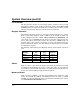
System Overview (cont’d) Fire Protection The fire protection portion of your security system (if used) is always on and will sound an alarm if a fire condition is detected. Refer to the FIRE ALARM SYSTEM section for important information concerning fire protection, smoke detectors and planning emergency exit routes from your house. Burglary Protection The burglary protection portion of your system must be turned on or "armed" before it will sense burglary alarm conditions.
System Overview (cont’d) Speed Key (Macros) The system can store a string of up to 32 keystrokes, which can be activated anytime by simply pressing the “A, B, C, or D” keys. This feature can be used to make it easy to perform multiple functions at once (such as going to another partition to bypass a zone), or it can be used to simplify an everyday, repeated procedure. Refer to the SPEED KEY section for procedures for using this feature.
System Overview (cont’d) Master Keypad Operation A "Master" keypad is one on which the status of all 8 partitions is displayed simultaneously. A user can get more information about a certain partition by simply entering [✳] + the desired partition number (1-8). To log on to the "Master" partition (9) using the GOTO command, and to perform any functions at a Master keypad, a user must have access to all partitions.
About The Keypads General IMPORTANT: If the keypad beeps rapidly upon entering the premises, it indicates that an alarm has occurred during your absence. LEAVE IMMEDIATELY and CONTACT THE POLICE from a safe location nearby. Your keypads allow you to control all system functions. The keypads feature a telephone style (digital) keypad and a Liquid Crystal Display (LCD) that shows the nature and location of all occurrences.
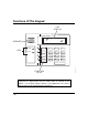
Functions Of The Keypad LCD DISPLAY SPEAKER ARMED A 1 OFF 2 AWAY 3 STAY READY B 4 MAX 5 TEST 6 BYPASS C 7 INSTANT 8 CODE 9 CHIME READY 0 D # FUNCTION KEYS IMPORTANT!: When using the keypad to enter codes and commands, sequential key depressions must be made within 3 seconds of one another. If 3 seconds elapses without a key depression, the entry is aborted and must be repeated from its beginning.
Functions Of The Keypad (cont’d) ALPHA DISPLAY WINDOW: A 2-line, 32-character Liquid Crystal Display (LCD). Displays protection point identification and system status, messages, and user instructions. 1 OFF : Disarms the burglary portion of the system, silences alarms and audible trouble indicators, and clears visual alarm trouble after the problem has been corrected.
Functions Of The Keypad (cont’d) 9 CHIME : Turns on & off the CHIME mode. When on, any entry through a protected delay or perimeter zone while the system is disarmed will cause a tone to sound at the Keypad(s). ✳ READY : When depressed prior to arming the system, the keypad will display all open protection zones within the keypad’s home partition. This key is also used to display all zone descriptors that have been programmed for your system, by holding the key down for at least 5 seconds.
Entry/Exit Delays General Information Your system has installer-programmed time delays, known as exit delay and entry delay. Whenever you arm your system, exit delay gives you time to leave through the designated exit door without setting off an alarm. Exit delay begins immediately after entering any arming command, and applies to all modes of arming protection. If programmed, a slow beeping will sound throughout the exit delay period.
Security Codes & Authority Levels General Information At the time of installation, you were assigned an authority level and a personal four-digit security code, known only to you and yours. The security code must be entered when arming and disarming the system. The authority level defines the system functions that you can perform.
Security Codes & Authority Levels (cont’d) Authority Levels Authority levels define the system functions a particular user can perform. Depending on the authority assigned to you, there are certain system functions you may be prohibited from performing. In summary, there are six authority levels, each having certain system restrictions as shown below. Level 1 Master: Can perform all system functions in assigned partitions, and can add, delete or change Manager and Operator level users.
Security Codes & Authority Levels (cont’d) General Rules on Authority Levels and Changes • A user may not delete or change the user code of the SAME or HIGHER authority than which he is assigned. • A user may only ADD users to a LOWER authority level. • A user may assign access codes only to those partitions to which the user adding the code has access. (ex. a user with access to only partition 1 cannot assign codes in partition 2.
Security Codes & Authority Levels (cont’d) To Add a User IMPORTANT: Temporary users should not be shown how to use any system function they do not need to know (e.g. bypassing protection zones). CODE 1. Enter Master or Manager code and press the 8 key. 2. Enter the new user’s 3-digit User Number (02-75). 3. Enter 4-digit security code for that user. The following prompts will appear. Enter 1 to add a new user code.
Security Codes & Authority Levels (cont’d) – 18 – MULTI-ACCESS ? 0 = NO , 1 = YES If you as a user have access to other partitions, the keypad will prompt for ability of this new user to access (GOTO) those partitions. Press 0 (NO) or 1 (YES). If no, the system activates this user code and exits “Add a User” mode. If yes, the keypad prompts for the Global Arm option for this user.
Security Codes & Authority Levels (cont’d) To Change a User’s Code CODE 1. Enter Master or Manager code and press the 8 key + user number to be changed. 2. Enter the new code for that user. ADD NEW USER? 0 = NO , 1 = YES USER 02 CHANGED SUCCESSFULLY The system will recognize that the user number is already in use and will prompt whether or not this is a new user. Enter 0 to change the existing user’s code to the code entered in step 3.
Accessing Other Partitions To Access Another Partition Each keypad is assigned a default partition for display purposes, and will show only that partition’s information. But, if the user is authorized, a keypad in one partition can be used to perform system functions in other partitions by using the GOTO command. Note that only those partitions authorized and programmed by the installer can be accessed in this manner. To GOTO another partition: READY 1.
Accessing Other Partitions (cont’d) ARM P 1 2 3 4 5 6 7 8 The prompt displays all the partitions. The user HIT 0-8 X X X - - X - - may only arm/disarm the partitions they are assigned access to. To select the partition(s) that are to be armed, enter the desired number 1-8. An "X" will appear under that partition. Entering a partition’s number again will delete the “X” and that partition will not arm when this prompt is exited. Pressing 0 will turn all partitions the user is assigned access to on/off.
Accessing Other Partitions (cont’d) Master Keypad Operation A "Master" keypad is one that reflects the status of the entire system (Partitions 1-8) on its display. This is useful because it eliminates the need for a security officer in a building to have to "log-on" to various partitions from one partition’s keypad to find out where an alarm has occurred.
Accessing Other Partitions (cont’d) Additional zone faults will be displayed one at a time. To display a new partition’s status, press ✴ + [Partition No.]. This will display the status of the new partition. The "Armed" LED on a Master keypad will be lit only if all partitions have been armed successfully. The "Ready" LED will be lit only if all partitions are "ready to arm." The sounder on a Master keypad will reflect the sound of the most critical condition on all of the partitions.
Accessing Other Partitions (cont’d) c. Arming the last partition programmed to arm the lobby will automatically attempt to arm the lobby. If any faults exist in the lobby partition, or another partition that affects the lobby is disarmed, the lobby cannot be armed, and the message “UNABLE TO ARM LOBBY PARTITION” will be displayed.
Checking For Open Zones Using the ✳ READY Key Before arming your system, all protected doors, windows and other protection zones must be closed or bypassed (see BYPASSING section). Otherwise the keypad will display a "Not Ready" message. Using the READY key will display all zones that are faulted, making it easier for you to secure any open zones. To show faulted zones: DISARMED - PRESS 7 TO SHOW FAULTS Note: Some keypads light a green LED when the system is ready.
Displaying All Zone Descriptors Using the ✳ READY Key The Alpha Keypads can also display all the zone descriptors that are programmed in your system. The abbreviated instructions for the READY key will appear first, followed by the zone descriptors. Displaying all descriptors is useful when you need to know the zone number of a particular zone, as when bypassing zones. The "Disarmed-Ready to arm" message must be displayed before zone descriptors can be displayed.
Bypassing Protection Zones Using the 6 BYPASS Key This key is used when you want to arm your system with one or more zones intentionally unprotected. Bypassed zones are unprotected and will not cause an alarm when violated while your system is armed. All bypasses are removed when an OFF sequence (security code plus OFF) is performed. Bypasses are also removed if the arming procedure that follows the bypass command is not successful. Note: The system will not allow fire or emergency zones to be bypassed.
Bypassing Protection Zones (cont’d) Quick Bypass Your system allows you to easily bypass all open (faulted) zones without having to enter zone numbers individually. Note: All bypasses are removed when an OFF sequence (security code plus OFF) is performed. To use the Quick Bypass feature: BYPASS 1. Enter your security code and press 2. BYPASS 007 FRONT UPSTAIRS BEDROOM Typical bypass message 3. DISARMED BYPASS READY TO ARM 6 then press # .
Arming Perimeter Only (With Entry Delay ON) Using the 3 STAY key Use this key when you are staying home, but might expect someone to use the entrance door later. When armed in STAY mode, the system will sound an alarm if a protected door or window is opened, but you may otherwise move freely throughout the premises. Late arrivals can enter through the entrance door without causing an alarm, but they must disarm the system within the entry delay period or an alarm will occur.
Arming Perimeter Only (With Entry Delay OFF) Using the 7 INSTANT Key Important: If you are using a Symphony (Advanced User Interface), NIGHT mode is the same as INSTANT. Use this key when you are staying home and do not expect anyone to use the entrance door. When armed in INSTANT mode, the system will sound an alarm if a protected door or window is opened, but you may otherwise move freely throughout the premises. The alarm will also sound immediately if anyone opens the entrance door.
Arming All Protection (With Entry Delay ON) Using the 2 AWAY Key Use this key when no one will be staying on the premises. When armed in AWAY mode, the system will sound an alarm if a protected door or window is opened, or if any movement is detected inside the premises. You may leave through the entrance door during the exit delay period without causing an alarm. You may also reenter through the entrance door, but must disarm the system within the entry delay period or an alarm will occur.
Arming All Protection (With Entry Delay OFF) Using the 4 MAXIMUM Key Use this key when the premises will be vacant for extended periods of time such as vacations, etc., or when no one will be moving through protected interior areas. When armed in MAXIMUM mode, the system will sound an alarm if a protected door or window is opened, or if any movement is detected inside the premises.
Disarming And Silencing Alarms Using the 1 OFF Key The OFF key is used to disarm the system and to silence alarm and trouble sounds. See "SUMMARY OF AUDIBLE NOTIFICATION" section for information which will help you to distinguish between FIRE and BURGLARY alarm sounds. IMPORTANT: If you return and the main burglary sounder is on, DO NOT enter the premises, but call the police from a nearby safe location.
Using The Keyswitch General Your system may be equipped with a keyswitch for use when arming and disarming a partition. A red and green light on the keyswitch plate indicate the status of your system as follows: Green Light: Lights when the system is disarmed and ready to be armed (no open zones). If the system is disarmed and the green light is off, it indicates the system is not ready (one or more zones are open). Red Light: Lights when system is armed or memory of alarm exists.
Chime Mode Using the 9 Key Your system can be set to alert you to the opening of a door or window while it is disarmed by using CHIME mode. When activated, three tones will sound at the Keypad whenever a protected perimeter door or window is opened, and the Not Ready message will be displayed. Pressing the READY key will display the open protection points. Note that Chime mode can be activated only when the system is disarmed. 1. To turn Chime Mode on, enter the security code and press 9 .
Viewing Alarm Company Messages General Information Users of the system may periodically receive messages on their display screens from their monitoring agency or installer. When a message is waiting to be viewed, the message shown below will appear. MESSAGE. PRESS 0 FOR 5 SECS. 1. Press and hold down 0 key for 5 seconds. 2. The message could take up to four screens to display all the information available. NOTE: Any message sent by the central station downloader may be viewed at any partition’s keypad.
Panic Keys (For Manually Activating Silent And/Or Audible Alarms) Using Panic Keys Your system may have been programmed to use special key combinations to manually activate panic functions. The functions that might be programmed are Silent Emergency, Audible Emergency, Personal Emergency, and Fire. See your installer for the function(s) that may have been programmed for your system. Active Panic Functions (Your installer should note which function(s) is active in your system.
Speed Key (Macros) General Information The “D” key can be used to activate a string of commands up to 16 keystrokes each. These commands are known as a macro and are stored in the system’s memory. Typical Speed Key functions include: • Arming sequences that involve first bypassing certain zones before arming. • Seldom used but repeatable sequences. • Relay activation sequences.
Speed Key (Macros) (cont’d) Executing To activate a Speed Key, press and hold down the [D] key for 2 seconds. If a user code is required for any part of the Speed Key sequence, the following prompt appears. Otherwise, the Speed Key sequence automatically begins. ENTER USER CODE 7777 Enter your user code. automatically.
Access Door Control General Information Your system may be set up such that a locked access door (such as in a lobby) can be unlocked momentarily or for a specific period of time, using a keypad command. Ask your installer if this has been done in our system. Executing There are several entries that can be entered at the keypad to activate this command: Enter your security code + [0]. The door will unlock for 2 seconds.
Using #70 Relay Menu Mode General Information Your system may be set up so that certain lights or other devices can be turned on or off by using the #70 command from either a keypad or a telephone keypad (if 4285 or 4286 VIP module is used). Ask your installer if this has been done in your system. To activate relays from a keypad, enter 4-digit security code + [#] +70. Follow the keypad prompts described below.
Using Schedules Delaying the Closing Time Your system’s programmed schedules may automatically arm the system at a predetermined time. In the event a user must stay on the premises later than usual, users with master or manager authority levels can manually delay the automatic arming (closing) time up to 2 hours. To delay the closing time: 1. Enter your security code (master or manager authority levels only). 2. Press the # key, followed by 82. 3.
Using Schedules (cont’d) Programming Temporary Schedules Temporary schedules only affect the partition from which it is entered. Temporary schedules can be reused at later dates simply by scrolling (by pressing #) to the DAYS? prompt (described below) and activating the appropriate days. This should be considered when defining daily time windows. Note that only users with authority level of manager or higher can program temporary schedules. To program temporary schedules: 1. Enter your security code. 2.
Using Schedules (cont’d) DAYS ? MTWTFSS HIT 0-7 X X This is the prompt that actually activates the temporary schedule, and allows the temporary schedule to be customized to a particular week’s needs. To select the days which are to be activated, enter the desired number 1-7 (Monday = 1). An "X" will appear under that day, indicating the previously entered schedule for that day is active. Entering a day’s number again will deactivate that day. Pressing 0 will turn all days on/off.
Programming Device Timers General Information Device timers consist of an ON time & an OFF time, and selected days of the week in which they are active. There are up to 20 timers that can be used to control various devices, such as lights or appliances. Your installer will have programmed the appropriate devices into the system (up to 16 devices can be programmed). Each timer controls a single device (designated as an output number) that you select.
Programming Device Timers (cont’d) 00 ON TIME ? 00:00 PM Enter the time you want the device turned on using 00:01 - 11:59 format. When the display shows the desired time, press the * key to move to the AM/PM field. Press any key 0-9 to change the AM/PM indication. Enter 00:00 if this timer is not being used to turn something ON for the days selected below. (ex. using one timer to turn lights on one day and using another timer to turn them off on another day).
Event Log Procedures General Information The system has the ability to record various events in a history log wherein each event is recorded in one of five categories (listed below), with the time and date of its occurrence. The Event Log holds up to 224 events, with the oldest event being replaced by the logging of any new event after the log is full. Using an alpha keypad, the Event Log can be viewed one category at a time, or can display all events, regardless of category (ALL EVENT LOG).
Event Logging Procedures (continued) 4. Use the [3] & [1] keys (for next and previous categories respectively) to display the categories of events. Press [8] to select a category and display the first event. Press [8] again for each subsequent event. Shows burglary alarm occurred in zone 3 (C03) of partition 1 (P1), at 12:02AM on January 1.
Testing The System (To Be Conducted Weekly) Using the 5 TEST Key The TEST key puts your system into Test mode, which allows each protection point to be checked for proper operation. 1. Disarm the system and close all protected windows, doors, etc. READY should be displayed. TEST 2. Enter your security code and press the 3. The external sounder should sound for 3 seconds and then turn off. If the sounder does not sound, it may be due to dialer communication activity. Wait a few minutes and try again.
Fire Alarm System Your fire alarm system (if installed) is on 24 hours a day, providing continuous protection. In the event of an emergency, the smoke and heat detectors automatically send signals to your Control, triggering a loud interrupting sound from the keypad and the optional exterior sounders. FIRE appears at your keypad and remains on until you silence the alarm. In Case Of Fire Alarm 1.
Trouble Conditions Typical Trouble Displays The word CHECK on the Keypad’s display, accompanied by a rapid "beeping" at the Keypad, indicates that there is a trouble condition in the system. To silence the beeping sound for trouble conditions, press any key. • A display of “CHECK” accompanied by a display of "CALL SERVICE" indicates that a problem exists with the system that eliminates some of the protection. CALL FOR SERVICE IMMEDIATELY.
Trouble Conditions (cont’d) Power Failure If the POWER indicator is off, operating power for the system has stopped and is inoperative. CALL FOR SERVICE IMMEDIATELY. If the POWER indicator is on, but the message "AC LOSS" is displayed, the Keypad is operating on battery power only. If only some lights are out on the premises, check circuit breakers and fuses and reset or replace as necessary. CALL FOR SERVICE IMMEDIATELY if AC power cannot be restored.
Recommendations For Proper Protection The following recommendations for the location of fire and burglary detection devices help provide proper coverage for the protected premises. Recommendations For Smoke And Heat Detectors With regard to the number and placement of smoke/heat detectors, we subscribe to the recommendations contained in the National Fire Protection Association’s (NFPA) Standard #72 noted below.
Recommendations For Proper Protection (cont’d) In addition, we recommend the following: Install a smoke detector inside every bedroom where a smoker sleeps. Install a smoke detector inside bedrooms where electrical appliances (such as portable heaters, air conditioners or humidifiers) are used. Install a smoke detector inside every bedroom where someone sleeps with the door partly or completely closed. Smoke could be blocked by the closed door.
Emergency Evacuation Establish and regularly practice a plan of escape in the event of fire. The following steps are recommended by the National Fire Protection Association: 1. Position your detector or your interior and/or exterior sounders so that they can be heard by all occupants. 2. Determine two means of escape from each room. One path of escape should lead to the door that permits normal exit from the building. The other may be a window, should your path be impassable.
Maintaining Your System Taking Care of Your System The components of your security system are designed to be as free of maintenance as possible. However, there are some things you can do to make sure that your system is in reliable working condition. 1. Test your system weekly. 2. Test the system after any alarm occurs (see TESTING THE SYSTEM).
Maintaining Your System (cont’d) Silencing Low Battery Warning Tones at the Keypad The keypad’s warning tones can be silenced by performing an OFF sequence (code plus OFF key), but the Keypad's low battery message display will remain on as a reminder that you have a low battery condition in one or more of your sensors. When you replace the weak battery with a fresh one, the sensor will send a "good battery" signal to the control as soon as the sensor is activated (opening/closing of door, window, etc.
Quick Guide To System Functions FUNCTION Check Zones Display All Descriptors Arm System PROCEDURE Press [✱]. Press and hold [✱] for 5 seconds. Chime Mode Enter code. Press arming key desired (AWAY, STAY, INSTANT, MAXIMUM). Enter code. Press OFF [1]. Enter code. Press BYPASS [6]. Enter zone numbers to be bypassed (use 3-digit entries). Enter code. Press BYPASS [6]. Press [#]. Enter code. Press CHIME [9]. Test Mode Enter code. Press TEST [5] View Messages Press and hold [0] for at least 5 seconds.
Quick Guide To System Functions (cont’d) FUNCTION Delete a User Control Output Device Access Control PROCEDURE Enter master/manager code. Press CODE [8]. Enter user no. to be deleted. Enter master/manager code. Press 1 (Yes) at prompt. Enter security code. Press [#] Enter 71 or 72. Enter security code. Press [#] Enter 70. Enter security code. Enter 0. Enter security code Press [#]. Enter 79. COMMENTS Master & Manager level users can delete users.
Summary Of Audible Notification (Alpha Display Keypads) SOUND CAUSE DISPLAY LOUD, INTERRUPTED* Keypad & External LOUD, CONTINUOUS* Keypad & External ONE SHORT BEEP (not repeated) Keypad only FIRE ALARM FIRE is displayed; descriptor of zone in alarm is displayed. BURGLARY/AUDIBLE EMERGENCY ALARM ALARM is displayed; descriptor of zone in alarm is also displayed. a. SYSTEM DISARM b. SYSTEM ARMING ATTEMPT WITH AN OPEN ZONE. c. BYPASS VERIFY ONE SHORT BEEP (once every 15 sec.
UL NOTICE: This is a “GRADE A” system. “FEDERAL COMMUNICATIONS COMMISSION (FCC) Part 15 STATEMENT” This equipment has been tested to FCC requirements and has been found acceptable for use. The FCC requires the following statement for your information: This equipment generates and uses radio frequency energy and if not installed and used properly, that is, in strict accordance with the manufacturer’s instructions, may cause interference to radio and television reception.
“FEDERAL COMMUNICATIONS COMMISSION (FCC) Part 68 NOTICE This equipment complies with Part 68 of the FCC rules. On the front cover of this equipment is a label that contains, among other information, the FCC registration number and ringer equivalence number (REN) for this equipment. If requested, this information must be provided to the telephone company. This equipment uses the following jacks: An RJ31X is used to connect this equipment to the telephone network.
CANADIAN DEPARTMENT OF COMMUNICATIONS (DOC) STATEMENT NOTICE The Canadian Department of Communications label identifies certified equipment. This certification means that the equipment meets certain telecommunications network protective, operational and safety requirements. The Department does not guarantee the equipment will operate to the user’s satisfaction.
WARNING! THE LIMITATIONS OF THIS ALARM SYSTEM While this system is an advanced design security system, it does not offer guaranteed protection against burglary or fire or other emergency. Any alarm system, whether commercial or residential, is subject to compromise or failure to warn for a variety of reasons. For example: • Intruders may gain access through unprotected openings or have the technical sophistication to bypass an alarm sensor or disconnect an alarm warning device. • Intrusion detectors (e.g.
Index #70 command.........................................41 4285 or 4286 VIP module...................8, 41 AC Loss ..................................................52 Access Another Partition ........................20 Access Door ...........................................40 ADD NEW USER....................................19 Add User Code .................................16, 17 Alarm ........................................................6 Alkaline batteries ....................................
POWER/READY INDICATOR ............... 12 Quick Arming.................................... 12, 14 Quick Bypass ......................................... 28 Quick Guide ..................................... 58, 59 Ready ............................................... 25, 35 Ready Key.............................................. 25 Relay Menu Mode .................................. 41 Replacing Batteries ................................ 56 RF BUTTON........................................... 17 Routine Care .
LIMITED WARRANTY Honeywell International Inc.
– 68 –
– 69 –
– 70 –
– 71 –
165 Eileen Way, Syosset, New York 11791 Copyright © 2004 Honeywell International, Inc. www.honeywell.com/security ¬1 9 #l N5943-6V2 5/04 Rev.