
Install Instructions


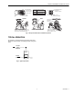


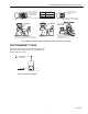

Table Of Contents

VP525A,C PNEUMATIC RADIATOR VALVE
INSTALLATION
ACTUATOR
VP525C CLOSE-OFF
SPRING RANGE
AT MAXIMUM SYSTEM PRESSURE
PSI (kPa)
Actuator Spring Selection
2-5
3-10
Series 2 VP525C Valves are built with a orange (3-10 psi)
actuator spring. Shipped with the valve is a loose green
(2-5 psi) spring. If desired, you can replace the orange spring
with the green. To make this change, you must remove the
cover fastener (see Fig. 1).
Threaded Union Body Version
Typical applications of straight-through and angle pattern
union connected valves are shown in Fig. 4. The direction of
flow must be toward the union connected end (the same
9
14
(62)
(97)
11
16
(76)
(110)
13
18
(90)
(124)
15
20
(103)
(138)
17
22
(117)
(152)
19
24
(131)
(165)
21
26
(145)
(179)
CONTROL AIR PRESSURE PSI (kPa)
C
v
= 2.0
C
v
= 0.63
C
v
= 3.0
C
v
= 5.0
direction as the arrow cast on the valve body).
23
28
(159)
(193)
Use proper piping methods when installing the threaded union
25
30
(172)
(207)
0 20 40 60 80 100 120 140
body to prevent distortion of the valve body (see Fig. 5).
(0) (138) (276) (414) (552) (689) (827) (965)
CLOSE OFF DIFFERENTIAL
The union tail piece, with the union nut in place, is attached to
PRESSURE RATINGS PSI (kPa)
C7714
A
the radiator with a suitable spud wrench. The valve body is
threaded into the supply piping then secured to the tail piece
Fig. 3. VP525C close-off ratings.
by means of the union nut.
ACTUATOR
VP525A CLOSE-OFF
SPRING RANGE
AT MAXIMUM SYSTEM PRESSURE
PSI (kPa)
2-5
3-10
7 12
(48) (83)
9
14
(62)
(97)
11
16
(76)
(110)
C
v
= 2.0
C
v
= 0.63
C
v
= 3.0
C
v
= 5.0
CONTROL AIR PRESSURE PSI (kPa)
13
18
(90)
(124)
STRAIGHT THROUGH ANGLE
M1644
8
15
(103)
17
(117)
19
(131)
21
(145)
23
20
(138)
22
(152)
24
(165)
26
(179)
Fig. 4. Threaded union body connections.
28
(159)
(193)
25
30
(172)
0
(0)
(207)
20
(138)
40
(276)
60
(414)
80
(552)
100
(689)
CLOSE OFF DIFFERENTIAL
PRESSURE RATINGS PSI (kPa)
120
(827)
140
(965)
C7713
A
Fig. 2. VP525A close-off ratings.
95-5544EF–1 2