
Install Instructions


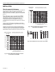


Table Of Contents

VP525A,C
Pneumatic Radiator Valve
INSTALLATION INSTRUCTIONS
A
A
E
B
B
C
C
D
D
2-1/4 DIAMETER (57)
2-1/4 DIAMETER (57)
AIR CONNECTION
FOR1/4 IN. (6 mm)
O.D. PLASTIC TUBING
AIR CONNECTION
FOR1/4 IN. (6 mm)
O.D. PLASTIC TUBING
COVER FASTENER COVER FASTENER
BEFORE INSTALLATION
This normally-open, single-seated, straight-through,
pneumatic valve provides two-position or proportional control
of two-pipe hot water or steam systems.
The valve can be installed in any position. The direction of
flow must be in the same direction as the arrow cast on the
valve body.
Refer to Fig. 1 for dimensions to determine the space required
for proper installation. Be sure to allow enough clearance
around the actuator top for servicing after installation.
1-1/2
(38)
1
1
1-1/2 in. (38 mm) MINIMUM CLEARANCE TO REMOVE
ACTUATOR. 2 1/2 in. (63 mm) MINIMUM CLEARANCE
TO FACILITATE STRAIGHT ON TUBING CONNECTION.
IF CLEARANCE IS LESS THAN 2 1/2 in. (63 mm)
USE AN ELBOW.
SPECIFICATIONS
Body Pressure Rating: 150 psi (1034 kPa) maximum.
Controlled Medium Temperature (maximum):
VP525A: 180°F (82°C) maximum.
VP525C: 240°F (116°C) maximum.
Maximum allowable difference (alternating hot and cold
water): 140°F (78K).
Maximum Safe Air Pressure: 30 psi (207 kPa).
Maximum Differential Pressure for Quiet Service:
Water: 20 psi (138 kPa).
Steam (VP525C): 10 psi (69 kPa).
Close Off Ratings:
VP525A: See Fig. 2.
VP525C: See Fig. 3.
1-1/2
(38)
1
BODY STYLE SIZE NPT
A
B C D E
STRAIGHT THRU œ
MALE UNION OUTLET
1/2
3-1/2 (90)
1-3/8 (35)
2-1/2
(63)
1-3/8 (35)
3/4
(19)
3/4
3-1/2 (90)
1-3/8 (35)
3
(76)
1-5/8 (41)
1-1/8
(29)
ANGLE œ MALE
UNION OUTLET
1/2
3-1/4 (83)
1 (25)
2-5/8
(66)
1-1/8 (29)
3/4
3-1/8 (80)
1 (25)
3
(76)
1-1/4 (32)
M16449A
Fig. 1. VP525 threaded union body dimensions in in. (mm).
® U.S. Registered Trademark
Copyright © 2002 Honeywell International Inc.
All Rights Reserved
95-5544EF-1