
Submittal Sheet


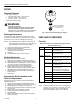


Table Of Contents

VP525A,C PNEUMATIC RADIATOR VALVES
75-5544EF 4
REPAIR
Equipment Required
• Thin, open-end wrench:
— For solder body valves: 1-1/4 in. wrench.
— For 1/2 in. valves: 1-1/2 in. wrench.
— For 3/4 in. valves: 1-1/4 in. wrench.
• Commercial cleaning solvent.
WARNING
Personal Injury Hazard.
Careless handling of solvents can permanently
injure the respiratory system and skin tissue.
Use solvents in a well ventilated area. Avoid prolonged
inhalation of solvents and/or contact with the skin.
Diaphragm Replacement
For faulty diaphragm, replace top (14003102-001, plastic
construction; or 14003648-001, metal construction). The top
consists of cover, connector, and diaphragm. See Fig. 7.
NOTE: Use 14003648-001 Top (metal) on steam when air
inlet is piped with copper tubing, or on jobs requiring
rugged installation such as exposed radiation.
1. Remove branchline tubing at actuator fitting.
2. Remove cover locking fastener.
3. Push down and turn cover counterclockwise to
disengage bonnet locking tabs.
4. Lift top off.
5. Install replacement top in reverse manner.
Packing Replacement
Repack valves without system shutdown:
1. Remove top (see Diaphragm Replacement section).
2. Disengage spring retaining cup and remove coil spring.
3. While holding stem in upper position, remove: packing
nut, packing, packing cup, and packing spring.
4. Clean all parts with commercial cleaning solvent.
5. Inspect valve stem for worn or scored areas. If
replacement is necessary, see Stem and Disc Holder
Assembly and/or Valve Seat Replacement section.
6. Reassemble components, including new packing, in
reverse manner.
7. Replace top.
Stem and Disc Holder Assembly and/or
Valve Seat Replacement
Shut down and remove pressure from the system before
disassembling valve:
1. Remove top (see Diaphragm Replacement section).
2. Disengage spring retaining cup and remove coil spring.
3. Remove packing nut and packing components.
4. Remove bonnet from valve body for access to the stem,
disc, and seat.
5. Inspect valve seat and replace if necessary.
6. Install new stem and disc assembly or top.
7. Insert assembly.
8. Reassemble all parts, connect actuator to branchline,
and turn on system.
Fig. 5. Top and insert assembly (see Table 2).
PARTS AND ACCESSORIES
Parts List
Table 2. Serviceline Kits—Replacement Top and Insert
Assemblies (See Fig. 5).
a
Replacement Top and Insert Assembly increases C
v
to 1.6.
NOTE: All Serviceline Kits include three color-coded springs
of ranges: 2-5, 3-10, and 8-11 psi (14-34, 21-69, and
55-76 kPa) as shown in Fig. 6, and replacement
seats where applicable (see Fig. 6 and Table 3).
Body Type Part Number Use With
Solder 14003299-001 VP525A1002, 1010, and 1028
(5/8 in. O.D. body, 1.6 C
v
).
14003300-001 VP525A1036, 1044, and 1051
(7/8 in. O.D. body, 2.5 C
v
).
Threaded 14003115-001
VP525A1069, 1077, 1085, 1390
a
, 1408
a
,
and 1416 (1/2 in. valves, 2.0 C
v
or less).
14003117-001 VP525A1143, 1150, and 1168
(3/4 in. valves, 3.0 C
v
).
14003118-001 VP525A1184, 1192, 1200, 1218, and 1226
(3/4 in. valves, 5.0 C
v
).
14003119-001 VP525A1093, 1101, 1127, 1119, and 1135
(1/2 in. valves, 3.0 C
v
).
VP525A1176: Field to replace stem and
plug on 14003119-001 with 14004553-003
14004897-001 VP525C1008 (1/2 in. valve, 0.63 C
v
).
14004897-002 VP525C1016, 1040 (1/2 in. valve, 2.0 C
v
).
14004897-003 VP525C1024, 1057 (3/4 in. valve, 3.0 C
v
).
14004897-004 VP525C1032, 1065 (3/4 in. valve, 5.0 C
v
).
14004897-005 VP525C1073, 1081 (1/2 in. valve, 3.0 C
v
).
C7994
SEAT NOT FURNISHED
ON 3.0 AND 3.5 CV MODE
L
1/2-IN. PIPE SIZE