
Instructions / Assembly


VR8245 AND VR8345 UNIVERSAL ELECTRONIC IGNITION GAS CONTROLS
69-2013—02 4
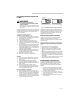
Fig. 2. Install sediment trap.
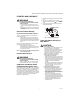
Install Gas Control
1. This gas control can be mounted from 0 to 90
degrees in any direction from the vertical position of
the gas control knob.
2. Mount the gas control so gas flow is in the direction
of the arrow on the bottom of the gas control.
3. Thread pipe the amount shown in Table 5 for inser-
tion into the gas control.
IMPORTANT:
Do not thread pipe too far. Valve distortion or
malfunction can result when the pipe is inserted
too deeply into the gas control.
4. Apply a moderate amount of good quality pipe com-
pound (do not use Teflon tape) to pipe only, leaving
two end threads bare. See Fig. 1. On LP installa-
tions, use compound resistant to LP gas.
5. Remove seals over gas control inlet and outlet if
necessary.
6. Connect pipe to gas control inlet and outlet. Use
wrench on the square ends of the gas control. See
Fig. 3 and 6.
When working with an intermittent pilot ignition system, go
to Connect Pilot Gas Tubing section next. When installing
on a hot surface or direct spark ignition system, go to the
Wiring section.
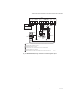
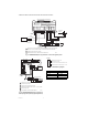
Fig. 3. Top view of gas control.
GAS
CONTROL
GAS
CONTROL
HORIZONTAL
DROP
PIPED
GAS
SUPPLY
PIPED
GAS
SUPPLY
3 IN.
(76 MM)
MINIMUM
3 IN.
(76 MM)
MINIMUM
3 IN.
(76 MM)
MINIMUM
RISER
GAS
CONTROL
TUBING
GAS
SUPPLY
HORIZONTAL
DROP
RISER
2
1
2
2
1
2
ALL BENDS IN METALLIC TUBING SHOULD BE SMOOTH.
CAUTION: SHUT OFF THE MAIN GAS SUPPLY BEFORE REMOVING
END CAP TO PREVENT GAS FROM FILLING THE WORK AREA. TEST
FOR GAS LEAKAGE WHEN INSTALLATION IS COMPLETE.
M8435A
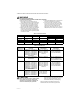
Table 5. NPT Pipe Thread Length in in.
Pipe
Size
Thread Pipe
This Amount
Maximum Depth Pipe Can
Be Inserted Into Control
3/8 9/16 3/8
1/2 3/4 1/2
3/4 13/16 3/4
INLET
INLET
OUTLET
HI
LO
OUTLET
PRESSU RE
TA P
PILO T O U TLET
PRESSURE REGULATOR
ADJUSTMENT
(UNDER CAP SCREW)
WIRING
TERMINALS (3)
INLET
PRESSURE TAP
PILOT ADJUSTMENT
()UNDER CAP SCREW)
GAS
CONTROL
KNOB
HI-LOW
ADJUSTMENT SCREWS
(UNDER CAP)
REGULATOR
VENT COVER
TWO-STAGE
PRESSURE
REGULATOR
MODEL
M10968B