
Instructions / Assembly


VR8245 AND VR8345 UNIVERSAL ELECTRONIC IGNITION GAS CONTROLS
9 69-2013—02
STARTUP AND CHECKOUT
WARNING
FIRE OR EXPLOSION HAZARD
CAN CAUSE PROPERTY DAMAGE, SEVERE
INJURY, OR DEATH
1. Do not force the gas control knob. Use only
your hand to turn the gas knob. Never use any
tools.
2. If the gas control knob will not operate by hand,
call a qualified service technician to replace the
gas control.
Gas Control Knob Settings
The gas control knob operates differently in intermittent
pilot, hot surface and direct spark ignition systems.
The gas control knob settings for an intermittent pilot
system are as follows:
OFF: Prevents pilot and main burner gas flow.
ON: Permits gas to flow into the control body.
Under control of the thermostat and intermittent
pilot module, gas can flow to the pilot and main
burner.
The gas control knob settings for hot surface or direct
spark ignition systems are as follows:
OFF: Prevents main burner gas flow.
ON: Permits main burner gas flow. Under control
of the thermostat and ignition module, gas can
flow to the main burner.
NOTE: Gas controls are shipped with the gas control
knob in the ON position.
Perform Gas Leak Test
WARNING
FIRE OR EXPLOSION HAZARD
CAN CAUSE PROPERTY DAMAGE, SEVERE
INJURY, OR DEATH
Check for gas leaks with a rich soap and water
solution anytime work is done on a gas control.
ZAdjust the Pilot Burner Flame
(Intermittent Pilot Ignition only)
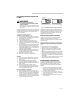
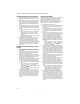
The pilot flame should envelop 3/8 to 1/2 in. [10 to 13 mm]
of the igniter-sensor tip. See Fig. 14. If the pilot flame is
small or lazy, or does not touch the ground electrode or
thermocouple, the inlet gas pressure may be too low, or
the pilot orifice may be partially clogged. Check and repair
as necessary. If the pilot flame is hard and noisy, the inlet
gas pressure may be too high. If pilot adjustment is
necessary, proceed as follows:
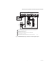
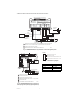
1. Remove the pilot adjustment cover screw. Refer to
Fig. 3.
2. Turn the inner adjustment screw clockwise to
decrease or counterclockwise to increase pilot
flame.
3. To prevent gas leakage, always replace the cover
screw after adjustment.
Fig. 14. Proper flame adjustment.
Check And Adjust Gas Input to
Main Burner
CAUTION
Fire or explosion hazard.
1. Do not exceed the input rating stamped on the
appliance nameplate, or manufacturer
recommended burner orifice pressure for the
size orifice(s) used. Make certain the primary
air supply to the main burner is properly
adjusted for complete combustion (refer to the
appliance manufacturer instructions).
2. WHEN CHECKING GAS INPUT BY
CLOCKING THE GAS METER:
• Make sure that the only gas flow through the
meter is that of the appliance being checked.
• Make certain that other appliances are turned
off with pilot burners extinguished (or deduct
that gas consumption from the meter
reading).
• Convert the flow rate to Btuh as described in
Gas Controls Handbook, form 70-2602, and
compare to the Btuh input rating on the
appliance nameplate.
3. WHEN CHECKING GAS INPUT WITH A
MANOMETER (PRESSURE GAUGE):
• To connect the manometer, be sure the gas
control knob is in the OFF position before
removing the outlet pressure tap plug.
• When removing the manometer, turn the gas
control knob back to OFF and replace the
outlet pressure tap plug.
• Shut off the gas supply at the appliance
service valve, or at the gas tank for LP gas,
before removing the outlet pressure tap plug
and before disconnecting the manometer and
replacing the outlet pressure tap plug.
• Perform the Gas Leak Test at the outlet
pressure tap plug.
PROPER FLAME
ADJUSTMENT
IGNITER-
SENSOR
M3080A
3/8 TO 1/2 INCH
(10 TO 13 mm)