W8835 EnviraZone Panel PRODUCT DATA FEATURES • Controls up to three stages heat and two stages cooling of single-stage, multi-stage, conventional, or heat pump. • Controls up to three zones and can be expanded up to nine zones with two W8703A DIM. • Uses VisionPRO® IAQ or FocusPRO communicating thermostats for manual or automatic changeover by zone. • Supports dehumidification, humidification and ventilator controls.
W8835 ENVIRAZONE PANEL SPECIFICATIONS Finish: W8835: Taupe cover, olive-gray base. Input Ratings: Voltage: 20-30 Vac, 50/60 Hz. Power: 11 VA nominal, Class II. Mounting: Mounts with four screws (provided) through holes in cabinet back (wall anchors provided). Output Ratings (dampers and HVAC equipment): 1.5A run, 200,000 cycles (30 Vac) 3.5A inrush. 1.5A run, 100,000 cycles (30 Vac) 7.5A inrush. Wiring: Eighteen-gauge wire for all equipment and system connections.
W8835 ENVIRAZONE PANEL Use SDCR for additional dampers required. If using RRD dampers, refer to RRD installation instructions for maximum number of dampers. Dampers: See Table 1 for suggested dampers. Dampers are connected to M1 Common, M4 Open, and M6 Closed (see Fig. 5 through 8 for hookups). Connect no more than five ARD or ZD dampers to an individual zone.
W8835 ENVIRAZONE PANEL Table 2. Required Accessories (Not Supplied with Panel). Accessory Bypass Rating (cfm) Description 40 VA transformers AT140A1042a — High and low limit sensor C7835A1009a — Round static pressure regulator damper SPRD7 SPRD8 SPRD9 SPRD10 SPRD12 SPRD14 SPRD16 300 400 600 750 1200 1800 2400 Rectangular static pressure regulator damper SPRD12x8 SPRD12x10 SPRD12x12 SPRD20x8 SPRD20x10 SPRD20x12 1000 1200 1400 1600 2000 3000 aSupplied in the Y8835 kits.
W8835 ENVIRAZONE PANEL Wiring Thermostats If separate HVAC equipment transformers are used for the heating and cooling systems, such as for an oil furnace, wire the heating transformer hot wire to Rh and the cooling transformer hot wire to Rc. Locate the Rh/Rc jumper above the equipment terminals and remove the jumper to expose the two pins. Run wire from the Thermostat 1, 2, 3 terminals to the corresponding terminals on any one of the EnviraCom bus terminal sets.
W8835 ENVIRAZONE PANEL For dual fuel equipment using heat pump and fossil fuel, configure the panel as a heat pump and use a fossil fuel kit. Do not use the dual fuel functionality of the VisionPRO® IAQ. Wiring HVAC Equipment SINGLE TRANSFORMER HEATING/COOLING SYSTEMS REQUIRE A JUMPER TO BE INSTALLED CONNECTING RH AND RC (FACTORY INSTALLED). HVAC EQUIPMENT L SINGLE TRANSFORMER HEATING/COOLING SYSTEMS REQUIRE A JUMPER TO BE INSTALLED CONNECTING RH AND R C (FACTORY INSTALLED).
W8835 ENVIRAZONE PANEL ARD or ZD Dampers Wire the ARD or ZD Damper to the panel as shown in Fig. 8. Multiple dampers can be wired in parallel. Up to five ARD or ZD dampers can be connected in parallel to one zone. If five to ten dampers are connected to the panel an additional 40VA transformer must be connected to the panel. ZONE 1, 2, 3 M6 M4 M1 M1 M6 M4 M1 M6 M4 M31134 Fig. 8. Wiring ARD or ZD damper to panel. Fig. 10. Wiring two RRD dampers in parallel.
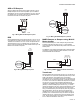
W8835 ENVIRAZONE PANEL 4. CAUTION Equipment Damage Hazard. Incorrect transformer wiring can damage panel. Wire transformers in phase when one transformer is wired to R and C and the auxiliary transformer is wired to T1 and T2. 5. 6. REMOVE XFRM JUMPERS FROM PINS WHEN USING TWO TRANSFORMERS 7. 24 VAC, 40 VA TRANSFORMER PANEL XFRM R C T1 T2 DAMPER XFRM 8. R C 9. NOTE: The furnace heat may not come on immediately. Allow at least 5 minutes for heat to begin after the thermostat calls for heat.
W8835 ENVIRAZONE PANEL COM LED Operation The green COM LED flickers as the W8835 communicates with the other EnviraCom devices: LED blinks rapidly—indicates device is currently transmitting information on the communications bus. LED blinks once—indicates device received and acknowledged a message. LED on constantly— indicates panel failure. Replace panel. LED off constantly—indicates a wiring problem. Table 3. LED Indicatorsb LED Color Illuminated Not Illuminated Heat Red Heat call. No heat calls.
W8835 ENVIRAZONE PANEL Heat Pump Operation Discovery The panel can control one or two compressor stages plus auxiliary heat. Set DIP switch 1 and 2 to Off; set DIP switch 7 to On for a single-stage compressor and to Off for a two-stage compressor. Discovery is an automatic system configuration program where the panel configures itself to operate with controls connected to the EnviraCom bus. The panel enters Discovery when the Discovery button on the panel is pressed. Rebooting Microprocessor Table 8.
W8835 ENVIRAZONE PANEL Discharge Air Temperature Sensor DATS When the circuit breaker is tripped, none of the LEDs illuminate and the yellow rectangular component located bottom center on the panel is hot to touch. The C7835A1009 Discharge Air Temperature Sensor (included in the Y8835 kits) is a supply-duct-mounted temperature sensor probe used to control capacity and prevent high plenum temperatures or coil-icing. The sensor is wired to the EnviraCom bus using three wires.
Table 12. DIP Switches 1 and 2 Equipment Type DIP 1 DIP2 On (up) On (up) 2 Stage Conventional On (up) Off (down) 3 Stage conventional Off (down) On (up) Heat Pump Off (down) Off (down) 1 Stage Conventional Table 13. DIP Switches 3–10 DIP Switch Function On (Up, Default) Off (Down) 3 Type of furnace Conventional/non-communicating EnviraCom Communicating 4 Purge time Two minutes 3.
W8835 ENVIRAZONE PANEL W8835A controlling a zone valve or circulator relay panel Jumper in place L FAN RELAY CENTER C 24 VOLT TRANS 2 C W8835A Rh R Rc W1/E W2 NOTE: FOR THE AQUASTAT AND CIRCULATOR WIRING, SEE THE INSTALLATION INSTRUCTIONS FOR THE HYDRONIC RELAY PANEL.
W8835 ENVIRAZONE PANEL W8835 for hot-water zone valves without a hydronic relay panel L C Rh Remove Rh/Rc jumper Cooling Rc R W1/E Y W2 G W3/AUX W8835A Y1 Y2 G THIS DIAGRAM SHOWS HOW THE W8835 GETS WIRED TO ZONE VALVES AND AN AIR-CONDITIONER FOR HOT WATER HEATING AND FORCED AIR COOLING APPLICATIONS.
W8835 ENVIRAZONE PANEL 15 68-0258—04
Automation and Control Solutions Honeywell International Inc. Honeywell Limited-Honeywell Limitée 1985 Douglas Drive North 35 Dynamic Drive Golden Valley, MN 55422 Toronto, Ontario M1V 4Z9 customer.honeywell.com ® U.S. Registered Trademark © 2009 Honeywell International Inc. 68-0258—04 E.K. Rev.
Panel EnviraZone W8835 INFORMACIÓN DEL PRODUCTO APLICACIÓN El panel EnviraZone W8835 controla equipos de una sola etapa, de varias etapas, convencionales o bombas de calor para calefacción y refrigeración. Controla tres zonas y puede ampliarse hasta nueve zonas con dos módulos adicionales de interfase del humidificador (DIM) W8703A. Para obtener información en Internet: http://yourhome.honeywell.com. Para obtener asistencia técnica, comuníquese al siguiente número: 1-800-828-8367.
PANEL ENVIRAZONE W8835 CARACTERÍSTICAS • Controla hasta tres etapas de calefacción y dos etapas de refrigeración en equipos de una sola etapa, de varias etapas, convencionales o bombas de calor. • Controla hasta tres zonas y puede ampliarse hasta nueve zonas con dos DIM W8703A. • Utiliza termostatos de comunicación VisionPRO® IAQ o FocusPRO para cambio automático o manual por zona. • Admite controles de deshumidificación, humidificación y ventilador.
PANEL ENVIRAZONE W8835 Accesorios: Para ver los accesorios necesarios, consulte la Tabla 2. Los accesorios opcionales incluyen el módulo de acceso telefónico W8735 para teléfonos con capacidad de marcación interna y externa, y el módulo de interfaz para regulador W8703 para el control de zonas adicionales. Reguladores: Consulte la Tabla 1 para ver los reguladores sugeridos. Los reguladores están conectados a M1 común, M4 abierto y M6 cerrado (ver Fig. 5 a 8 para las conexiones).
PANEL ENVIRAZONE W8835 Tabla 2. : Accesorios necesarios (no incluidos con el panel).
PANEL ENVIRAZONE W8835 Cableado de los termostatos Si se utilizan transformadores individuales de equipo HVAC para los sistemas de refrigeración y calefacción, de igual manera que para un sistema de calefacción a gas, conecte el hilo caliente del transformador de la calefacción a Rh y el hilo caliente del transformador de la refrigeración a Rc. Coloque el puente Rh/Rc sobre los terminales del equipo y quite el puente para exponer las dos clavijas.
PANEL ENVIRAZONE W8835 Si el equipo de la bomba de calor tiene un terminal L que se activa en caso de falla de la bomba, conéctelo al terminal L del equipo y conecte C, en la parte izquierda del panel, al terminal común HVAC. Cuando se activa el terminal L, los termostatos iluminan la calefacción de emergencia. Para equipos de combustible dual que utilizan una bomba de calor y combustible fósil, configure el panel como bomba de calor y utilice un juego de combustible fósil.
PANEL ENVIRAZONE W8835 Reguladores ARD o ZD ZONA 1, 2, 3, ETC. M6 M4 M1 Conecte el regulador ARD o ZD al panel, tal como se muestra en la Fig. 8. Se pueden conectar varios reguladores en paralelo. Se pueden conectar hasta cinco reguladores ARD o ZD en paralelo a una zona. Si al panel se conectan de cinco a diez reguladores, se deberá conectar un transformador de 40 VA adicional al panel.
PANEL ENVIRAZONE W8835 Transformador Conecte los transformadores al panel (ver Fig. 12). Se necesita un transformador de 40 VA, 24 V CA para hacer funcionar el panel y hasta cinco reguladores ARD o ZD. El transformador se conecta a los terminales R y C. Si se conectan hasta diez reguladores al panel, se necesitará el transformador auxiliar. El transformador auxiliar se conecta a los terminales T1 y T2.
PANEL ENVIRAZONE W8835 FUNCIONAMIENTO El panel W8835 activa el equipo HVAC, y se envía aire acondicionado a la zona de la orden. El LED de calefacción (rojo), de refrigeración (verde) o del ventilador (verde) se iluminan para indicar el funcionamiento del equipo. Secuencia de funcionamiento Cuando no existe una orden de calefacción, refrigeración o ventilador, el tablero estará en el modo suspendido (ningún LED del sistema está iluminado); vea la Tabla 3.
PANEL ENVIRAZONE W8835 Control del ventilador para zona individual Cuando todas las zonas se encuentran a gusto, el interruptor del ventilador de cada termostato controla el funcionamiento del ventilador de esa zona. Cuando la configuración del ventilador esté en "On" (Encendido), el ventilador se activa, el LED del ventilador se ilumina y los reguladores se cierran en las zonas donde la configuración del ventilador está en "Auto" (automático).
PANEL ENVIRAZONE W8835 a esto, los terminales R y C del transformador en el W8835 no se utilizan. En cambio, deje los puentes XFMR en su posición predeterminada desconectada y conecte los transformadores T1 y T2. Tabla 9.
PANEL ENVIRAZONE W8835 SOLUCIÓN DE PROBLEMAS Tabla 11. Solución de problemas. Síntoma Posible causa Solución Ningún LED está iluminado No hay suministro de energía Controle que haya 24 V CA (± 10%) en R y C. en el tablero. Los LED del humidificador están Encendido (hacia arriba)s, pero los demás LED no están iluminados. Funcionamiento irregular. Los transformadores están fuera de fase. Si hay 48 V CA en R y T1, invierta los cables de T1 y T2. Cable en cortocircuito.
PANEL ENVIRAZONE W8835 W8835A CONTROLA UN PANEL DE RELÉS DEL CIRCULADOR O DE LA VÁLVULA DE ZONA PUENTE INSTALADO CENTRO DEL RELÉ DEL VENTILADOR 2 C W8835A L C TRANS. DE 24 VOLTIOS Rh R Rc W1/E W2 NOTA: PARA EL AQUASTAT Y EL CABLEADO DEL CIRCULADOR, VEA LAS INSTRUCCIONES DE INSTALACIÓN PARA EL PANEL DE RELÉS HIDRÓNICOS.
PANEL ENVIRAZONE W8835 W8835 PARA VÁLVULAS DE ZONA DE AGUA CALIENTE SIN UN PANEL DE RELÉS HIDRÓNICOS L C Rh QUITE EL PUENTE Rh/Rc Enfriamiento Rc R W1/E Y W2 G W3/AUX W8835A Y1 ESTE DIAGRAMA MUESTRA CÓMO CONECTAR EL W8835 A LAS Y2 VÁLVULAS DE ZONA Y UN AIRE ACONDICIONADO PARA APLICACIONES DE CALEFACCIÓN DE AGUA CALIENTE Y DE ENFRIAMIENTO DE AIRE FORZADO. PARA VER EL CABLEADO COMPLETO DEL AQUASTAT, G CONSULTE LAS INSTRUCCIONES PARA EL AQUASTAT.
PANEL ENVIRAZONE W8835 15 68-0258ES—04
PANEL ENVIRAZONE W8835 Automatización y control desenlace Honeywell International Inc. Honeywell Limited-Honeywell Limitée 1985 Douglas Drive North 35, Dynamic Drive Golden Valley, MN 55422 Toronto, Ontario M1V 4Z9 customer.honeywell.com ® Marca Registrada en los E.U.A (C) 2009 Honeywell International Inc. todos Los Derechos Reservados 68-0258ES—04 E.K. Rev.