WebVision™ USER GUIDE PRODUCT DESCRIPTION WebVision™ is a web-based building manager that allows contractors and facility managers to view and command HVAC controllers installed at their sites. It communicates over the LonWorks® network to perform building management control of various devices and controllers through a web browser. The WebVision Bundle (WWS-VL1A1000) includes the WebVision controller pre-installed with a LON communications card, and power supply.
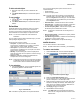
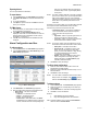
WEBVISION™ FEATURES • Support up to 120 XL10s, XL15Cs, VFDs, and 3rd Party LON devices • Perform Auto Discovery and Wizard based configuration of controllers • Support Default Alarms on each device • Support Default Trends on each device • Support default device graphic for each device 2. 3. 4. To log off from WebVision: — • Configure a maximum of 30 users and define their roles in accessing and configuring devices and WebVision Type your WebVision login name in the User Name field. Type your Password.
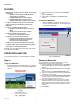
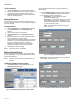
WEBVISION™ Fig. 4. Graphics Tab. Fig. 3. Password Reminder screen. TIP: The information you provide is validated against the information present in the WebVision database. If the information is correct, WebVision will send the user ID and password to your E-Mail account. TIP: If you do not remember the password recovery information and the answer provided by you is incorrect, you can request the WebVision Administrator to reset your password.
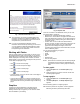
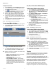
WEBVISION™ To insert a background image: To insert text: 1. NOTE: The supported background image formats include: jpg, jpeg, and gif. Click the Insert Text button. A Text Message box appears. The size of the image file must not exceed 1MB. 1. Click the Insert Background Image button. The Insert Background Image dialog box appears. Fig. 7. Text Message Box. 2. 3. Fig. 5. Insert Background Image dialog box. 2. 3. Type the required text in the Edit Text field.
WEBVISION™ To delete selected objects: 1. 2. Use one of the following filter options to search for the required schedule: • Schedule Name • Current Occupancy State Select the object that you want to delete from the graphic. Click Delete Selected objects. The selected object is deleted. To copy graphics: 1. 2. Click the button. The Copy Graphics From dialog box appears. Click Delete Selected objects. The selected object is deleted.
WEBVISION™ To edit a schedule: 1. 2. 3. All the special events along with a summary appear in a tabular format. Click the Schedule tab. A list of schedules appears. Click the schedule that you want to edit by clicking the corresponding link in the Schedule Name column. Follow the steps described in the above sections and make the required changes. 2. 3. Assign Devices You can select a number of devices and assign them to a current configuring schedule. You can change the settings as and when required.
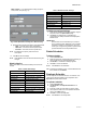
WEBVISION™ Week and Day – If you select Week and Day, specify the month, week, and year (Fig. 14). Table 2. Default Canadian Holidays. Name Day New Year’s Days January 1st Canada Day July 1st Labour Day The first Monday in September Thanksgiving Day The second Monday in October Remembrance Day November 11th Christmas Day December 25th Boxing Day December 26th To add the pre-configured holidays: 1. 2. Fig. 14. Add Special Event dialog box - Week and Day. 4.
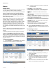
WEBVISION™ Alarms NOTE: Select the check box in the header row to select all the listed alarms. Viewing alarms • Alarm Name – List of all alarm names. • Device Name – Lists all devices on which alarms are set. To view the details of any device, click the respective device. • Description – Indicates the condition that raised the alarm. • Occurrence Time – Indicates the date and time when the alarm was raised. • Priority – Indicates the priority level of an alarm.
WEBVISION™ Exporting Alarms down list. The selected values are reflected in the Alarm Setup screen. Type a Display Name for the point. You can export alarms on WebVision. To export alarms: 1. 2. 3. 4. Click the Alarms tab. The View Alarms page appears. Click Export All Alarms to download all the alarms at once. A .csv file is displayed. Click Open to open the file and click Save to save the file on your computer. To E-Mail alarms: 1. 2. 3.
WEBVISION™ To replicate an alarm: Add, Edit, or Delete Alarm E-Mail Recipient 1. 2. Click the Alarms tab. The View Alarms page appears. Click the Alarm Setup tab on the View Alarms page. The Alarm Setup page appears. 3. Click corresponding to the alarm that you want to replicate. The Replicate Alarm dialog box appears. Type the alarm name in the Alarm Name text box. Select an alarm and device that you want to replicate from the Replicate Alarm and Device drop-down list.
WEBVISION™ trends stored in WebVision. You cannot delete these sample trends. However, you can create new trends. The trends created by you are called User Defined trends. When you add a device, all the default trends present in that device are added to WebVision. All the default trends are disabled. You can create and view a maximum of 100 trends. To view trends: Click the Trends tab.
WEBVISION™ Trend Setup and Use The sampling interval time can range from a few seconds to a few minutes. The range covered is: • 15 seconds • 30 seconds • 60 seconds (1 minute) • 900 seconds (15 minutes) • 1800 seconds (30 minutes) • 2700 seconds (45 minutes) • 3600 seconds (60 minutes) • Change of Value – Indicates that the next sample is collected when the point value changes. This results in less number of samples getting collected for plotting the same trend as compared to Periodic Sampling.
WEBVISION™ Users Table 3. Role Matrix. (Continued) Privilege ID Privileges You can create a maximum of 30 user profiles. You must be familiar with User ID and Password security standards to enforce user compliance when creating a user profile. As WebVision is a secure server, you need to log in with a preassigned user ID and password. The user ID and password combination determine your access level, which in turn determine the kind of operator and configuration functions performed.
WEBVISION™ Table 3. Role Matrix. (Continued) Table 3. Role Matrix.
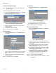
WEBVISION™ View list of Users To add a user: The list of users provides information on WebVision users such as their names, roles, and e-mail IDs. 1. On the Users page, click the Add User button. The Properties page appears. To view the list of users: 1. Click the Users tab. The Users page appears. Fig. 22. Add User - Properties page. 2. Fig. 21. Users page. TIP: Use Filters to quickly search the required user.
WEBVISION™ 5. Click the Access on this WebVision tab. The Access on this WebVision page appears. You can select various options from Device Access, Schedule Access, and Locations View Access. Check Select All to select all the options simultaneously. To view the list of devices: 1. Click the Devices tab. The Device List page appears. The following information appears in a tabular format: Use this option to assign customized access to users. Fig. 24. Devices Tab - Device List page. Fig. 23.
WEBVISION™ • Device Name – Name of the device. • Channel – The channel on which the device is present. • Device Type – Type of the device. • Model – Type the model number of the device. • Application Type – Type of application that is required for the selected device. • Application Version – Type the version of application used. • Application File – Application that must run on the device. Click Browse to upload an application file.
WEBVISION™ 4. 4. Click OK to confirm the deletion. TIP: To delete all devices at once, check the All check box in the header and click Delete. Set Mode to Auto NOTE: Click Cancel to abort the action. Sometimes when debugging a device, you set the mode to manual. The Set Mode to Auto feature is a simple option to set the devices back to auto mode. Device Binding To set the devices to auto mode: 1. 2. 3. 5. 6. Click the Devices tab. The Device List page appears.
WEBVISION™ 3. Click Download. The binding settings are downloaded on the selected channel. To upload device bindings: 1. 2. 3. Point groups are used for monitoring and diagnostics of controllers. You can create a maximum of fifty point groups in WebVision and add a maximum of fifty points to each point group. To view point groups: Click the Devices tab. The Device List page appears. Click the Point List tab. The Point List page appears with points present in the first point group.
WEBVISION™ • Save – Any change done in the UI is automatically saved locally in the Web UI. To save the modified configuration in the WebVision click Save. To write the saved data onto device, use the Device Download option. Balancing This process helps the VAV devices to calibrate their flow sensors for better air flow control. NOTE: To perform balancing ensure that the VAV device is online. Set Points To view the Balancing page: NOTE: The Setpoints tab appears only for the supported devices. 1. 2.
WEBVISION™ To perform Min/Max Balancing: The following are the two types of loads that DLC sheds to maintain demand below the peak setpoint: Complete the following procedure to do min/max balancing. NOTE: To do min/max balancing ensure that the VAV device is online. 1. 2. 3. 4. 5. 6. 7. 8. 9. Damper position and Sensed airflow displays the current damper position and flow sensed by the device. Click the Start Zero Balance to attain the zero flow setpoint.
WEBVISION™ Load Shedding Method 1. 2. 3. 4. The DLC starts shedding by first searching for all the Off Continuous loads that are eligible for shedding. Then, it first sheds the lowest numbered Off Continuous load and waits the staging interval to see if the demand has reduced. If the demand is still above the peak setpoint, then DLC sheds another Off Continuous load. This process continues until the demand is well within the peak setpoint limits.
WEBVISION™ 5. seconds and at the end of a staging interval, compares the power consumption with that of the active demand setpoint and the dead band. • Dead Band: Enter the dead band in the Dead Band text box. The dead band peak value is 1000. Click Save to save the settings. To add a Load: 1. 2. Table 4. (Continued)Load Shed Methods. If you have selected the Load Shed Method as… Rotating Load Click the DLC tab. The DLC Status page appears. Click the Load Assignment tab.
WEBVISION™ issuing a restore command even if the load assignments are in the shed state. After re-loading the configuration, all the Minimum On/Shed timers are also reset. NOTE: When DLC is in the Reloading Configuration mode, only the status of the load assignments is displayed. It implies that the respective load objects are not displayed. • Admin • System Utilization To configure the System general properties: Use the following procedure to configure the system general properties: 1.
WEBVISION™ 3. 4. 5. Choose US English or Metric as the standard for setting the Engineering Units. All the point values in the WebVision user interface are shown in the selected unit. For local weather, check the Enable check box. Select a State and City from the corresponding lists. Click Save to save the settings. To configure Site setup: Use the following procedure to configure the site setup: 1. 2. 3. Click the Systems tab. The System page with General Properties appears. Click the Site Setup tab.
WEBVISION™ 4. To enable Dial In settings: • Channel Info: (continued) • Domain Length: Length of the Domain ID. Click Save to save the settings. Complete the following procedure to enable the dial in settings on your computer/laptop: To configure Dial-up settings: 1. Use the following procedure to configure the dial-up settings: 1. 2. 3. 4. Click the Systems tab. The System page with General Properties appears. Click the Dial-Up Setup tab. The Dial-Up Setting page appears.
WEBVISION™ 4. 7. Select the Connect to the Internet option and click Next. Fig. 38. Connection Name - Service Provider. Fig. 35. Network Connection Type screen. 5. Type the name of the service provider and click Next. Select the Set up my connection manually option and click Next. 8. Type your phone number and click Next. Fig. 39. Phone Number to Dial screen. 9. Fig. 36. Setup my connection manually - button 6. Select the Connect using a dial-up modem option and click Next.
WEBVISION™ 10. server and domain names prior to configuring the SMTP E-mail server option. An example to maintain the format: SMTP.server.com. • Email Address: Enter a valid e-mail address. The account must be present in the SMTP server. • User Authentication: Check this box to provide the user credentials. On selection it enables the following parameters. • User Name: Type the user name of the SMTP server. Type any name of your choice. For example, webvision1. • Password: Type the SMTP password.
WEBVISION™ 1. 2. 3. Click Restore Configuration to restore the configuration settings from the backup file. The Restore Configuration dialog box appears. Select the backup file that has to be restored. Click Restore. WebVision restores the file and automatically logs out before starting to restore. Once restoring is complete, WebVision automatically reboots. This may take about 5 to 10 minutes. Logon to WebVision again, after 5 to 10 minutes.
WEBVISION™ 8. 9. 10. Alarm Dial-Out – This feature is not supported by WebVision or by any alternate mechanisms. Hence this has to be dropped as part of migration process. Runtime Logs - This feature is not supported by WebVision or by any alternate mechanisms. Hence this has to be dropped as part of migration process. Bindings between XL15A and RIOs – XL15A can be replaced with XL15C to drive the loops configured. If the loops are driving RIOs, the same be achieved using XL15Cs and RIOs.
WEBVISION™ LONSPEC METRIC VALUES LonSpec downloads metric values to the controller. WebVision does not do any unit conversion of XL15C configuration values when displaying in the user interface. Therefore, what the user gets to see is what is present in the controller. The following step eases the comparison process: 1. To fix the configuration error, use the following procedure: 1. Open the configuration of each XL15C and go to Control Loops tab.
WEBVISION™ LONSpec Changes Complete the following steps for migrating the existing LCBS sites to WebVision: 1. Ensure that LonSpec database which is used to commission the site is ready. Open the LonSpec project. Click Network > Edit on the menu bar. The Edit Network dialog box appears. NOTE: When re-commissioning, please use full commission command, not quick commission. 6. After re-commissioning, disconnect LonSpec from the network.
WEBVISION™ 12. Click Upload to upload the LON binding information onto WebVision. A progress bar appears indicating the progress of the Upload operation. NOTES 1. 2. 3. 4. 5. 6. Ensure all the devices are in Auto mode. If you see any device in Manual or any other mode, select that device and click Set Mode to Auto to change the mode. Click Download in Devices > Device List or Devices > Device Bindings to initiate the process of writing configuration data that is present in WebVision to devices.
WEBVISION™ APPENDIX A – SUPPORTED DEVICES This appendix provides configuration information for the following controllers and devices: • W7763C/D/E Chilled Ceiling Controller (CHC) ....page 34 • Constant Volume Air Handling Unit Controller (CVAHU) ..............................................................page 43 • Fan Coil Unit Controller (FCU) ............................page 54 • Hydronic Controller (HYD) ..................................page 64 • Excel 10 Remote Input/Output Device (RIO) ......
WEBVISION™ Table 7. Input/Output Detail. (Continued) Fan fail When configured with an air flow detector, the controller protects equipment by disabling the system when the fan fails (for fan coil units with manual fan speed control). Changeover The controller operates two-pipe units configured with a changeover input.
WEBVISION™ Table 8. CHC Outputs - Field Definitions. (Continued) Name Definition Application (continued) No Condensation Protection Disable the dew-point temperature calculation and protection. The cold water temperature and the humidity are not needed by the controller; the chilled ceiling protection can still be performed by the condensation switch. System Define the type of equipment that is being controlled in terms of the number of pipes used on the unit. Two Pipe A unit that has only two pipes.
WEBVISION™ Table 8. CHC Outputs - Field Definitions. (Continued) Name Definition Control Outputs (continued) Three Stage A three-stage switched output. Terminals 14/17 are switched for stage 1, terminals 15/18 are switched for stage 2. Both terminal 14+15 and/or 17+18 are switched for stage 3. Thermal A switched on/off output for switching a 24V thermal actuator on terminal 14/17. Output 2 - Mode The output triac pair connected to terminals 16/17/18 of the controller.
WEBVISION™ Table 9. CHC Inputs - Field Definitions. (Continued) Name Field and Definition Controller / Wall Module (continued) LED Occupancy The LED shows the effective Occupancy mode. On indicates effective Occupied or Bypass, 1 Flash per Second indicates effective Standby, Off indicates effective Unoccupied. 4 Flashes indicates the Controller answers of the Network Management Command Wink. LCD Display This mode is used only for a Wall Module with LCD Display.
WEBVISION™ Table 9. CHC Inputs - Field Definitions. (Continued) Name Field and Definition Input Ports Specifies usage of the controller inputs Analog Input 1 and Analog Input 2a Window Closed Indicates if a window is closed. Close window disables the controller operation. If the contact is closed, the window is closed. Window Open Indicates if a window is opened. An open window enables the controller operation. If the contact is closed, the window is closed.
WEBVISION™ CHC Equipment Control Procedure 1. Purpose Define the main control features of controller outputs. 2. 3. Mode 4. Configuration can be performed with the wizard Off-line or On-line. Click the Equipment Control button on the left pane to open the Equipment Control Configuration page. Enter information into available fields. Click Commit to save the settings or Reset to revert to the last saved settings.
WEBVISION™ CHC Switching Levels 3. 4. Purpose To configure the staged output switching levels. Click Commit to save the settings or Reset to revert to the last saved settings. Click Next to display the Miscellaneous Configuration page or Back to display the Switching Levels Configuration page. Mode CHC Zone Control fields Configuration can be performed with the wizard Off-line or On-line. Setpoints can range from 10 to 35 ºC (50 to 95 ºF). Procedure 1. 2. 3. 4.
WEBVISION™ Table 11. CHC - Miscellaneous Options. (Continued) Name Option and Definition Energy Management DLC SetPoint Bump For load shedding applications, define the temporary setpoint shift to be added to the setpoint when the controller receives a Load Shedding command. By raising the setpoint during cooling operation, or reducing the setpoint during heating operation, the controller reduces the amount of heat or cool energy dissipated as a contribution to load shed algorithms.
WEBVISION™ CHC Wiring Diagram Table 14. CHC - LON Bus Terminals. (Continued) Output1 / Output2 Purpose 3-stage Display the wiring diagram for the controller. Mode Terminal 14/15 Terminal 17/18 14 On = stage 2 17 On = stage 1 15 On = stage 2 18 On = stage 2 Configuration can be performed with the wizard Off-line or On-line.
WEBVISION™ Table 15. XL10 CVAHU Device Properties for each Model.
WEBVISION™ 7. 8. Choose the number of cooling stages (1-4) or the type (PWM or Floating) from the Cooling list. Select the type of economizer from the Economizer list. a. If the heating, cooling, or economizer is configured as PWM, the Period, Zero Scale, and Full Scale settings must be configured. b. If the heating, the cooling, or the economizer is configured as Floating, the Motor speed settings must be configured. 9. 10. 11. Configure the Optional points.
WEBVISION™ CVAHU Inputs Table 17. CVAHU Outputs Fields. (Continued) Name Motor Speed Definition You can configure three Motor Speed settings: • Heating • Cooling • Economizer Description If you select HeatingFloating for configuring Heating settings, Motor speed for heating is enabled. Enter all inputs to be wired to the CVAHU. To select the wall module type, voltage and resistive inputs for a CVAHU application.
WEBVISION™ Table 19. CVAHU Inputs Fields. (Continued) Name Optional Digital Inputs Table 19. CVAHU Inputs Fields. (Continued) Definition Name You can configure digital inputs. The W7750A can be configured with a maximum of two digital inputs. The W7750B, W7750B Enhanced, and the W7750C, can be configured with all four digital inputs. CoilfreezeStat is available on W7750C only.
WEBVISION™ Table 21. CVAHU Equipment Control Fields. (Continued) Table 20. Use Wall Module vs. Override Priority. Sensor Sensor only Use Override Priority Use Wall in Module as Setpoint in Miscellaneous Parameter Zone Option page page No Name Cascade Control Yes is available only if both a Discharge Air Temperature sensor and modulating heating or cooling are configured. Meaning None Use Wall Module as Sensor only Sensor Yes Setpoint None Use Wall module as Sensor as well as get set point.
WEBVISION™ CVAHU Economizer Table 22. CVAHU Economizer Fields. (Continued) Name Purpose Minimum Position of Damper used when poor Indoor Air Quality conditions exist (IAQ sensor > IAQ Setpoint, or if Digital IAQ Switch is on). Select a value from 0 to 100 percent. Use Heat for IAQ Enable or disable heat. • Yes enables heat when damper is open for IAQ purposes. • No disables heat if controller is in Cool mode. Define the four settings for using an economizer in a CVAHU application.
WEBVISION™ CVAHU Zone Options CVAHU HC Stages fields Table 23 lists the CVAHU HC Stages fields. Purpose Table 23. CVAHU HC Stages Fields. Name Minimum On/Off Configure CVAHU Controller zone options such as cooling and heating setpoints (temperature settings). Definition MinHeatOn enables minimum on/off time. MinHeatOff replaces set minimum on/off times with a 30-second default. MinCoolOn enables minimum on/off time. MinCoolOff replaces set minimum on/off times with a 30-second default.
WEBVISION™ Table 25. CVAHU Miscellaneous Fields. (Continued) Table 24. CVAHU Zone Options Fields. (Continued) Name Max. Limit Setpoint Name Definition Provides an upper limit on the allowed settings of the setpoint knob of the Wall Module. Enabled if Wall Module Setpoint is configured (Input tab). Values range from -9 to 9, (Setpoint default set to OFFSET) or from 50 to 90 (Setpoint default set to ABSOLUTE_MIDDLE).
WEBVISION™ CVAHU PID discharge sensors or wiring are in noisy environments and the value reported to the controller is not stable (such that it bounces). The Control Band is used only in modulating control, and has no purpose when staged control is configured. Purpose Adjust PID (Proportional Integral Derivative) control parameters for the CVAHU. CVAHU PID fields Mode Table 26 lists the CVAHU PID fields. Configuration can be performed with the wizard Off-line or On-line. Table 26. CVAHU PID Fields.
WEBVISION™ CVAHU Custom Wiring CVAHU Wiring Diagram Configuring CVAHU Custom Wiring Purpose Use the CVAHU Custom Wiring page to assign configured outputs to physical pins. Display the wiring diagram for the controller. Mode Purpose View or modify sensor output wiring locations. Configuration can be performed with the wizard Off-line or On-line. Mode Procedure Configuration can be performed with the wizard Off-line or On-line. 1. 2. 3.
WEBVISION™ Configuring Fan Coil Unit Controllers (FCU) Supported Output Types Table 30 lists the supported output types for the FCU Controller. Description Table 30. FCU Controller Output Types. The W7752 D, E, F, and G Controllers are communicating mains-powered Fan Coil Unit Controllers in the Excel 10 product line. They cover a wide range of fan coil control applications. The controllers can operate as stand-alone units or networked using the standard Echelon LONWORKS bus.
WEBVISION™ • Fan fail When configured with an air flow detector, the controller protects equipment by disabling the system when the fan fails FCU Input/Output Specifications Purpose Table 31 lists the FCU Input/Output specifications. Define the operation of the controller outputs and the type of fan coil unit to be controlled. Table 31. FCU Input/Output Specifications.
WEBVISION™ Table 32. FCU Outputs - Fields and Definitions. Field Types Definition FCU Select the hardware version to be used for the controller. The different hardware versions have different combinations of inputs and outputs. See the inset table below. The type of hardware you select affects the choices that appear in the rest of the pages for FCU. Based on your hardware selection, the configuration software ensures that you cannot configure a controller for an application it cannot perform.
WEBVISION™ Table 32. FCU Outputs - Fields and Definitions. (Continued) Field Control Outputs Definition Configures the two control outputs for the different type of actuators and control sequences required for the application. Output 1 Mode The output triac pair connected to terminals 13, 14, and 15 of the controller. Select the control sequence option for Output 1. For four-pipe applications, the heating option is recommended to minimize field wiring errors.
WEBVISION™ FCU Inputs fields Table 33 lists the FCU Inputs fields and definitions. Table 33. FCU Inputs Fields. Name Definition Wall Configures the functionality of the connected wall module. Always ensure that the features configured here are the Module same as the features available on the wall module device to be connected. Space Temp Sensor Specify whether or not the controller is to be used with a space temperature sensor connected to its input.
WEBVISION™ Table 33. FCU Inputs Fields. (Continued) Name Definition Wall Setpoint Module Knob (cont.) The setpoint knob is available in different types of scales, and with different setpoint meanings, based on the country of usage. The temperature engineering unit used (°C or °F) is the setting made in WebVision when creating the new project. This setting is used for the total project. NOTE: The setpoint knob only affects the Occupied and Standby Setpoints.
WEBVISION™ Table 33. FCU Inputs Fields. (Continued) Name Definition Digital Input Points (continued) Movement This selection is used for movement detector configuration where a closed contact indicates movement. Movement detector is the same as occupancy sensor, but with an additional Hold Time of 15 minutes. This adds a delay to the occupancy signal such that the space is considered occupied until 15 minutes has elapsed since the last movement is detected.
WEBVISION™ Table 34. FCU Equipment Control Options. (Continued) Name Definitions Output Options (continued) Min Stage Off Time Define the minimum off-time for control outputs configured for operation as staged outputs. This setting is particularly useful for heat exchanger operation or compressor units. Each stage of the controlled output stays off for the minimum period of time before the controller turns it on again. The selectable range is 0 to 600 seconds.
WEBVISION™ FCU Switching Levels Table 36. FCU Zone Control Options. (Continued) Name Purpose To configure fan switching level and staged output switching levels. Mode FCU Miscellaneous Configuration can be performed with the wizard Off-line or On-line. Purpose To configure energy management parameters. Procedure 1. 2. 3. 4. Click the Switching Levels button on the left pane to open the Switching Levels Configuration page. Enter information into available fields.
WEBVISION™ Table 38. FCU PID Options. (Continued) Table 37. FCU Miscellaneous Field Options. (Continued) Name Name Definitions Energy Cool.Rec.Ramp, Heat.Rec.Ramp Management Define the rate at which the setpoint is reset (continued) during changes between occupancy modes to provide a form of optimum start algorithm. Thermal Switching Band/PID Boost FCU PID Purpose Configure the variables for closed loop control. PID parameters can be set separately for both heating and cooling control.
WEBVISION™ Configuring Hydronic Controllers (HYD) LON Bus The terminals in Table 40 are used to connect the LON Bus FTT-10A. The LON terminals are insensitive to polarity, eliminating wiring errors during installation. Recommended wire size is level IV 22 AWG nonshielded, twisted pair, solid conductor wired.
WEBVISION™ Heat and cool sequences can be selected to be active or not active, giving a total of four different sequence options: • Heat only • Cool only • Heat/cool changeover • Heat and cool sequence Modes Of Operation The controller has the following modes of operation. Occupied mode This is the normal operating condition for a room or zone when it is occupied. The controller can be switched into this mode by a network command, by the room occupancy sensor, or by a bypass button on the wall module.
WEBVISION™ HYD Outputs fields Table 43. Hydronic Controller Types and Outputs. Name Types Definition HYD Select the hardware version to be used for the controller. Each hardware version has different combinations of inputs and outputs. The software checks Type against the controller's selected application so that you cannot configure a controller for an application that it cannot perform.
WEBVISION™ Table 43. Hydronic Controller Types and Outputs. (Continued) Name Definition Control Output 2- Mode Outputs Output triac pair connected to terminals 16/17/18 of the controller. (cont.) Select the control sequence option to be allocated to output 2. For four-pipe applications, always allocate this output to the cool option to minimize field wiring errors. For two-pipe applications, you can select only the changeover option. Output 2- Type Selection options are the same as for Output 1.
WEBVISION™ Table 44. Wall Module and Hydronic Controller Inputs. (Continued) Name Definition Wall Override Button Module Define how the override button on the connected wall module is to be used. (cont.) NO_BUTTON The wall module button is not used for the bypass function. BYPASS_UNOCCUPIED The Bypass button, when pressed, has two different functions depending on the length of time the button is held down: Two seconds puts the controller in Bypass. Five seconds puts the controller in Unoccupied.
WEBVISION™ Table 44. Wall Module and Hydronic Controller Inputs. (Continued) Name Digital Input Points Definition Specifies usage of the controller's digital input. Digital Input 1. DI_WINDOW_CLOSED Indicates if a window is opened. An open window disables the controller operation. If the contact is closed, the window is closed. DI_WINDOW_OPEN Indicates if a window is opened. An open window disables the controller operation. If the contact is closed, the window is open.
WEBVISION™ HYD Outputs fields Table 45. Hydronic Controller Outputs Fields. Name Definition Output Defines the operating characteristics of the two valve actuator outputs, Output 1 and Output 2 as configured in the Options Outputs tab. The settings for both Outputs have the same meaning as described in the following text. Valve Direction Define the operating direction of the valves for actuator types Floating, PWM, and Thermal. DIRECT To open, the valve is modulated from 0% to 100%.
WEBVISION™ HYD Miscellaneous Parameters Procedure 1. Purpose 2. 3. To configure miscellaneous and energy management parameters. 4. Mode Configuration can be performed with the wizard Off-line or On-line. Click the Miscellaneous button on the left pane to open the Miscellaneous Configuration page. Enter information into available fields. Click Commit to save the settings or Reset to revert to the last saved settings.
WEBVISION™ Table 47. Hydronic PID Parameters. (Continued) Name Thermal Switching Band/PID Boost Definition Cooling/Heating Boost Temp Sets a boost band for normal PID operation and when using thermal actuators. The variables indicate a setpoint-space temperature deviation outside which the outputs are switched to full operation to act as a boost function when space temperature deviates significantly from the desired setpoint.
WEBVISION™ Configuring the Excel 10 Remote Input/Output Device (RIO) Procedure 1. 2. 3. Description The W7761A Excel 10 Remote Input/Output Device (RIO) is a LonMark compliant device designed to monitor and control HVAC equipment, lighting, and other miscellaneous loads in a distributed network. Usage 4. Click the Input_pane button on the left pane to open the Input Configuration page. Enter information into available fields.
WEBVISION™ Mode 4. Configuration can be performed with the wizard Off-line or On-line. 5. Procedure 1. 2. 3. 4. Click the Output_pane button on the left pane to open the Output Configuration page. Enter information into available fields. Click Commit to save the settings or Reset to revert to the last saved settings. Click Next to display the Delta Configuration page or Back to display the Input Configuration page. 6. 7.
WEBVISION™ UV Outputs Table 53. Unit Ventilator Outputs. (Continued) Use Table 53 to configure the Unit Ventilator Outputs for heating and cooling stages. The outputs could be of stages, PWM, or floating types. In addition, the number of fan speeds and Economizer types must be set. You can also select optional points. Name Economizer Purpose Select all outputs, including optional outputs, to be controlled by the Unit Ventilator Controller.
WEBVISION™ Procedure 1. 2. 3. 4. Table 54. Unit Ventilator Inputs. (Continued) Click the Input button on the left pane to open the Input Configuration page. Enter information into available fields (see Table 54 on page 76). Click Commit to save the settings or Reset to revert to the last saved settings. Click Next to display the Equipment Control Configuration page or Back to display the Output Configuration page.
WEBVISION™ Procedure 1. 2. 3. 4. Table 55. .Unit Ventilator Control Options. (Continued) Click the Equipment Control button on the left pane to open the Equipment Control Configuration page. Enter information into available fields. Click Commit to save the settings or Reset to revert to the last saved settings. Click Next to display the Economizer Configuration page or Back to display the Input Configuration page.
WEBVISION™ Table 56. Unit Ventilator Economizer Settings. (Continued) Name OA Damper Min Pos IAQ Position Definition Minimum position of the Outdoor Damper (0 to 100%). Under normal Occupiedmode operation, the dampers are not closed below this setting. If Unoccupied, or if a Discharge Low Temperature condition exists, the dampers are closed below this setting. 1. This field is enabled only when Enable Type is set to Single Enth(alpy).
WEBVISION™ UV Zone Options Table 58. Unit Ventilator Zone Options. (Continued) Use Table 58 to configure the Unit Ventilator Zone Options to set the heating and cooling setpoints. Purpose Name Max. Limit Setpoint Enter all outputs, including optional outputs, to be controlled by the Unit Ventilator Controller. Mode Configuration can be performed with the wizard Off-line or On-line. UV Miscellaneous Settings Procedure 1. 2. 3. 4.
WEBVISION™ Table 59. Unit Ventilator Miscellaneous Settings. Name Override Priority CAUTION Definition Equipment Damage Possible Can cause short cycling of compressors or wide swings in space temperature and excessive overdriving of modulating outputs. If a large or frequent change to the PID control parameters is made, it is possible to cause equipment problems such as short cycling compressors (if the stage minimum run times were disabled).
WEBVISION™ Table 60. Unit Ventilator PID Settings. (Continued) Name Cooling Integral Time Table 60. Unit Ventilator PID Settings. (Continued) Definition Name Integral Time Determines what impact the error-over-time has on the output signal. Error-over-time has two components that make up its value: the amount of time the error exists and the size of the error. The higher the integral time, the slower the control response.
WEBVISION™ UV Controller Wiring Diagram • Also Digital Outputs: 8 configurable digital Triac outputs. (24 Vac & 500 mA). Purpose Navigating to Excel 10 VAV II pages Display the wiring diagram for the UV controller. Mode Configuration can be performed with the device Off-line or On-line. Procedure 1. 2. 3. 4. Click the Wiring Diagram button on the left pane to open the Wiring Diagram Configuration page. Enter information into available fields.
WEBVISION™ Table 62. Excel 10 VAV II - Configuration Parameters. (Continued) Name Box Type Definition Defines the physical type of VAV Terminal the controller is connected to. This select determines what control options are available for the VAV Terminal. Valid selections for this field are: • Single Duct – This VAV Terminal type consist of a single primary air supply inlet connection with or without a primary flow sensor.
WEBVISION™ Table 62. Excel 10 VAV II - Configuration Parameters. (Continued) Name Definition Output Settings Section Flow Type Defines the control flow algorithm used by the controller. The selection available dependents of the Pressure Type and Box Type selected. Valid selections for this field are: • Flow Normal – This flow type is selectable when the Pressure Type is set to pressure independent and the Box Type is set to Single Duct or Dual Duct.
WEBVISION™ Table 62. Excel 10 VAV II - Configuration Parameters. (Continued) Name Definition Output Settings Section (continued) Reheat Type (continued) • Float Periph Then Reheat – There is a modulating valve for the VAV Terminal reheat and a modulating valve for the space peripheral reheat. This option uses the series 60 type floating control for both valve outputs. The peripheral valve is modulated as the first stage of reheat and the VAV Terminal reheat valve is modulated open as the second stage.
WEBVISION™ Table 62. Excel 10 VAV II - Configuration Parameters. (Continued) Name Definition PWM Settings Section PWM Period Defines the time period of the PWM signal. This is usually the sum of the Zero time value and the Full Time value. The minimum resolution of the time value is 0.1 seconds. PWM Zero Defines the time period for the Zero position pulse. When the on time of the PWM period is at this value the PWM device will position itself to the zero position.
WEBVISION™ Excel 10 VAV II – Control Parameters Use Table 64 to configure the Excel 10 VAV II Control Parameters. Purpose Define Equipment Control parameters that the Excel 10 VAV II controller uses to control the unitary equipment. Define VAV II controller parameters. Mode 4. Configuration can be performed with the device On-line or Off-line. 1. Procedure 2. 3. Mode Procedure Configuration can be performed with device On-line or Off-line. 1. parameters.
WEBVISION™ Excel 10 VAV II Flow Pickup fields Excel 10 VAV II MIscellaneous Settings fields Table 66. VAV II Flow Pickup Fields. Name Table 67. VAV II MIscellaneous Settings. Definition Name Pt 1 through Pt 10 Ten pairs of airflow values (Inw [Differential pressure] and FPM [velocity]) Flow Sensor Type List of tables that contains manufacturers' specifications for airflow units. Each table has 10 pairs of airflow values versus feet per minute or feet per second.
WEBVISION™ Procedure 1. 2. 3. 4. 5. 6. Click the Custom Wiring button on the left pane to open the Custom Wiring page. You can choose to change the default assignment. Select Custom option in the Assignment Type list. Select Default to revert back to the default assignment. The number of outputs available for changing the configuration depends on the model type. For a W7751B Smart, only 4 output pins would be enabled. Click Commit to save the settings or Reset to revert to the last saved settings.
WEBVISION™ It is mandatory to set the option to Fieldbus for NXVFD to consider the frequency setpoint from the wizard. This configuration can be performed using the Key Pad control provided along with device as follows: • In the keypad, from the main menu, select the menu called Parameters. • Select the submenu I/O Reference and set it to FieldBus.
WEBVISION™ Table 69. NXVFD Drive Parameters. (Continued) Point Name Default Drive Speed Scale Min. Max. Value Value Typical Value -163.84 163.83 0% Each Analog Input may be configured as Analog or Digital. Analog Inputs configured as Analog can receive Input from various types of sensors.
WEBVISION™ • 20KNTC • Digital Active Short • Digital Active Open NOTE: The Analog Inputs may be configured as analog or digital. d. Select an Engineering Units. This list is enabled when the Analog Input is configured as Resistive or Voltage. The measurement types are listed here. When you select an Engineering Units option, the corresponding Engineering unit appear in the Sensor fields. e. Type the Input Low, Input High, Output Low and Output High.
WEBVISION™ Purpose The control portion of the loop is an Enhanced PID (EPID) algorithm. The user configures control algorithm type (PID or Non-linear), bias (position of set point within the proportional band (i.e. 0% or 50%), direct/reverse acting output, which sensor and outputs to use, throttling range, integral time, derivative time, start up ramp time, recovery, reset and sequencer parameters, set points, minimum on, off and bypass times, DLC shed bump and lead/lag.
WEBVISION™ • Setpoint Override: A configured setpoint overrides the existing setpoint if the corresponding Digital Input is TRUE. The Digital Input1 maps to Setpoint1, Digital Input2 maps to Setpoint2, vice versa. b. Loop Configuration • Reset: Control loops allow the setpoint (only in occupied mode) to reset either in the direction of increased energy savings or in the direction of the increased comfort. The reset of a control loop is dependent on the analog reset sensor input.
WEBVISION™ Purpose • On Delay Time: The delay in time for switching from one state to another before the output value switches to ON. • Off Delay Time: The delay in time for switching from one state to another before the output value switches to OFF. • DCAO: Digital Compare Analog Output - Sets the output value to equal analog input_1 if digital input is true and analog input_2 if the digital input is false. DCAO must be configured if the Logic Loop analog output is to be used.
WEBVISION™ 7. Select the following time options: • Min On Time: Default minimum on time for equipment is 5 minutes. Enter new value, if necessary, according to manufacturer’s recommendations. Specified range is 0 to 254 minutes. • Min Off Time: Default minimum off time for equipment is 5 minutes. Enter new value, if necessary, according to manufacturer’s recommendations. Specified range is 0 to 254 minutes. • Bypass time: Default bypass time is 180 minutes.
WEBVISION™ Configuring the T7350 Thermostat Controller (T7350) • KeyPad/Display • Setpoints • Equipment Control The T7350 is a full-featured Commercial programmable thermostat. The primary opportunity for a Commercial thermostat is in buildings with less than 55,000 square feet. These buildings include restaurants, shopping malls, office buildings and banks. Commercial thermostats are used on single zone rooftop units, split systems, heat pumps or hot/ chilled systems.
WEBVISION™ Table 70. T7350 General Configuration Fields (Continued) Name Room Temp Definition This option allows the user to configure the source of room temperature input to the thermostat. The T7350 thermostat is equipped with its own internal room temperature sensor. The sensor operating range is 30 to 110 °F.
WEBVISION™ Table 70. T7350 General Configuration Fields (Continued) Name Daylight Savings Definition Use this option to configure the settings for daylight savings. The following describes each field: Enable Daylight Savings: This option is enabled by default. Disable this option if the daylight savings feature is not required to be followed by the thermostat. Deselecting this option will disable the Start Month, Stop Month, Start Day and Stop Day fields.
WEBVISION™ Table 70. T7350 General Configuration Fields (Continued) Name Definition Heat/Cool Stages (continued) When the model is selected as T7350H1009 and the equipment type as Standard, the tool allows to configure for up to three stages of heating and three stages of cooling. The fourth stage of cooling is available for selection as long as the 0/1/2 heat stages are selected. When the fourth stage of cooling is selected, the third stage of heating is no longer available.
WEBVISION™ Keypad/Display Configuration fields Mode Configuration can be performed with the wizard Off-line or On-line. Table 71. Keypad/Display Configuration Fields. Name Keypad Lockout Display Units Definition Use this option to configure the keypad lockout enable/disable through special keypad sequence on the thermostat. Enable All: Selecting this option will allow the user to access any keys on the thermostat. No lockout will be imposed.
WEBVISION™ Table 72. Heating and Cooling Setpoints. (Continued) Setpoint Heat Standby Stpt Min. and Default Max. Value Ranges Description Any combination of the following 3 strategies is allowed: 67 °F 40-90 °F Standby heating setpoint (19 °C) (4-32 °C) • Display resolution: 1 °F/°C. • Unoccupied Heat <= Standby Heat <= Standby Cool -2 °F (1 °C) Heat 55 °F 40-90 °F Unoccupied heating setpoint Unoccupied (13 °C) (4-32 °C) • Display resolution: Stpt 1 °F/°C.
WEBVISION™ MINIMUM RAMP RATE Minimum Cool and heat recovery ramp rates are selectable from 0 to 20 DDF/hr. (0 to 11 DDC/hr.). A ramp rate of 0 means no recovery ramp (the setpoint steps from one setpoint to the other). The recovery ramp rate will vary as a function of outdoor temperature. MAX RAMP RATE Maximum Cool and heat recovery ramp rates are selectable from 0 to 20 DDF/hr. (0 to 11 DDC/hr.). A ramp rate of 0 means no recovery ramp (the setpoint steps from one setpoint to the other).
WEBVISION™ T7350 Equipment Control fields Table 73. T7350 Equipment Control Fields. Name Definition Heating Fan On with Heat Selections This field specifies the selection of fan operation OFF with Heat The equipment (i.e. plenum switch) controls the fan operation in heat mode. The thermostat controls the fan operation in cool mode. ON with Heat The thermostat controls the fan operation in both heat and cool modes.
WEBVISION™ Table 73. T7350 Equipment Control Fields. (Continued) Name Loop Tuning Definition This section allows the user to configure the loop tuning parameters. Throttling Range Use this screen to configure the heat and cool throttling ranges. The wizard automatically modifies the heat and cool throttling ranges when the number of stages configured is changed.
WEBVISION™ APPENDIX B – DEVICE POINT TABLES This appendix provides a table for the points detail and a table for the application of points of the following controllers and devices: • W7763C/D/E Chilled Ceiling Controller (CHC) .. page 106 • Constant Volume Air Handling Unit Controller (CVAHU) ..............................................................page 114 • Fan Coil Unit Controller (FCU) ........................... page 122 • Hydronic Controller (HYD) .................................
WEBVISION™ Table 74. CHC Point Details.
WEBVISION™ Table 75. CHC Application of Points. (Continued) Point Name Graphics Alarms Trends Commandable Internal Use Valid Values Standby Heat (Setpoint) X Units=ºC Precision=2 Min=10.0 Max=35.0 Unoccupied Heat (Setpoint) X Units=ºC Precision=2 Min=10.0 Max=35.0 Current State X Default Occupied Unoccupied Bypass Standby Next State X Default Occupied Unoccupied Bypass Standby Time To Next State X Units=min Precision=0 Min=0.0 Max=65535.
WEBVISION™ Table 75. CHC Application of Points.
WEBVISION™ Table 75. CHC Application of Points.
WEBVISION™ Table 75. CHC Application of Points. (Continued) Point Name Graphics Alarms Trends Commandable Internal Use Valid Values DLC Shed X X X Restored or Shed Economizer Output X X X Units=% Precision=1 Min=-163.8 Max=163.
WEBVISION™ Table 75. CHC Application of Points.
WEBVISION™ Table 75. CHC Application of Points. (Continued) Point Name Graphics Alarms Trends Commandable Internal Use Valid Values Scheduled Occupancy X X X Default Occupied Unoccupied Bypass Standby Secondary Heat Output X X X Units=% Precision=1 Min=-163.8 Max=163.8 Sensor Occupancy X X X Default Occupied Unoccupied Bypass Standby Space Temperature X X X Units=ºC Precision=1 Min=-273.2 Max=327.7 Terminal Load X X X Units=% Precision=1 Min=-163.8 Max=163.
WEBVISION™ Constant Volume Air Handling Unit Controller (CVAHU) Table 76 provides the CVAHU points detail and Table 77 on page 115 provides the CVAHU application of points. Table 76.
WEBVISION™ Table 76.
WEBVISION™ Table 77. CVAHU Application of Points. (Continued) Point Name Graphics Alarms Trends Commandable Internal Use Valid Values Unoccupied Cool (Setpoint) X Units=ºC Precision=2 Min=10.0 Max=35.0 Occupied Heat (Setpoint) X Units=ºC Precision=2 Min=10.0 Max=35.0 Standby Heat (Setpoint) X Units=ºC Precision=2 Min=10.0 Max=35.0 Unoccupied Heat (Setpoint) X Units=ºC Precision=2 Min=10.0 Max=35.
WEBVISION™ Table 77. CVAHU Application of Points. (Continued) Point Name Graphics Alarms Trends Commandable Internal Use Valid Values Application Mode X X X X Default Auto Heat Morning Warmup Cool Night Purge Pre-cool Off Test Emergency Heat Fan Only Free Cool Ice Maximum Heat Economy Dehumidify Calibrate Emergency Cool Emergency Steam Max Cool HVAC Load No Load Manual Mode X X X X Enable Disable Manual Suppress Alarms Unsuppress Alarms Set Discharge Air Config. Clear Discharge Air Config.
WEBVISION™ Table 77. CVAHU Application of Points. (Continued) Point Name Graphics Alarms Trends Commandable Internal Use Valid Values Cool Position X X X Units=% Precision=0 Min=-128.0 Max=127.0 Cool Stages On X X X Units=null Precision=0 Min=0.0 Max=7.
WEBVISION™ Table 77. CVAHU Application of Points. (Continued) Point Name Graphics Alarms Trends Commandable Internal Use Valid Values Discharge Air Temperature X X X Units=ºF Precision=1 Min=-256.0 Max=256.0 Discharge Setpoint X X X Units=ºF Precision=1 Min=-256.0 Max=256.0 Economizer Enable X X X Default Off Low Medium High On Economizer Float Synch X X X Off or On Economizer Position X X X Units=% Precision=0 Min=-128.0 Max=127.
WEBVISION™ Table 77. CVAHU Application of Points. (Continued) Point Name Mode Graphics Alarms Trends Commandable Internal Use X X X Valid Values Startup Wait Heat Cool Off Disabled Emergency Heat Smoke Emergency Freeze Protect Manual Factory Test Fan Only Monitor Switch X X X Off or On Monitor1 X X X Units=V Precision=1 Min=-32.0 Max=32.
WEBVISION™ Table 77. CVAHU Application of Points. (Continued) Point Name Graphics Alarms Trends Commandable Internal Use Valid Values Return Air Temperature X X X Units=ºF Precision=1 Min=-256.0 Max=256.0 Scheduled Occupancy X X X Default Occupied Unoccupied Bypass Standby ShutDown X X X False or True Smoke Monitor X X X False or True Space Co2 X X X Units=ppm Precision=0 Min=0.0 Max=65535.0 Space Temperature X X X Units=ºF Precision=1 Min=-256.0 Max=256.
WEBVISION™ Fan Coil Unit Controller (FCU) Table 78 provides the FCU points detail and Table 79 on page 123 provides the FCU application of points. Table 78.
WEBVISION™ Table 78.
WEBVISION™ Table 79. FCU Application of Points (Continued) Point name Graphics Alarms Trends Commandable Internal Use Valid Values Next State X Default Occupied Unoccupied Bypass Standby Time To Next State X Units=min Precision=0 Min=0.0 Max=65535.
WEBVISION™ Table 79.
WEBVISION™ Table 79.
WEBVISION™ Table 79. FCU Application of Points (Continued) Point name Graphics Alarms Trends Commandable Internal Use Valid Values Effective Occupancy X X X Default Occupied Unoccupied Bypass Standby Effective Sensor Occupancy X X X Default Occupied Unoccupied Bypass Standby Effective Window Open X X X Closed or Open External Active X X X Inactive or Active Fan Feedback X X X Failure or Running Fan Output X X X Units=% Precision=1 Min=-163.8 Max=163.
WEBVISION™ Table 79. FCU Application of Points (Continued) Point name Graphics Alarms Trends Commandable Internal Use Valid Values FCU Status Mode X X X Disabled Cool Heat Pressurize Depressurize Manual Mode Factory Test Mode Floating Out of Sync Fan Switch Off Startup Wait Output Position 0 X X X Units=% Precision=1 Min=-163.8 Max=163.8 Output Position 1 X X X Units=% Precision=1 Min=-163.8 Max=163.8 Primary Heat Output X X X Units=% Precision=1 Min=-163.8 Max=163.
WEBVISION™ Hydronic Controller (HYD) Table 80 provides the HYD points detail and Table 81 on page 130 provides the HYD application of points. Table 80. HYD Point Details.
WEBVISION™ Table 80. HYD Point Details.
WEBVISION™ Table 81. HYD Application of Points. (Continued) Point name Graphics Alarms Trends Commandable Internal Use Valid Values Next State X Default Occupied Unoccupied Bypass Standby Time To Next State X Units=min Precision=0 Min=0.0 Max=65535.
WEBVISION™ Table 81. HYD Application of Points.
WEBVISION™ Table 81. HYD Application of Points.
WEBVISION™ Table 81. HYD Application of Points. (Continued) Point name Graphics Alarms Trends Commandable Internal Use Valid Values Effective Occupancy X X X Default Occupied Unoccupied Bypass Standby Effective Sensor Occupancy X X X Default Occupied Unoccupied Bypass Standby Effective Window Open X X X Closed or Open External Active X X X True or False Fan Feedback X X X Failure or Running Fan Output X X X Units=% Precision=1 Min=-163.8 Max=163.
WEBVISION™ Table 81. HYD Application of Points. (Continued) Point name Graphics Alarms Trends Commandable Internal Use Valid Values HYD Status Mode X X X Disabled Cool Heat Pressurize Depressurize Manual Mode Factory Test Mode Floating Out of Sync Fan Switch Off Startup Wait Output Position 0 X X X Units=% Precision=1 Min=-163.8 Max=163.8 Output Position 1 X X X Units=% Precision=1 Min=-163.8 Max=163.8 Primary Heat Output X X X Units=% Precision=1 Min=-163.8 Max=163.
WEBVISION™ Excel 10 Remote Input/Output Device (RIO) Table 82 provides the RIO points detail and Table 83 on page 136 provides the RIO application of points. Table 82. RIO Point Details.
WEBVISION™ Table 83. RIO Application of Points. (Continued) Point Name Graphics Alarms Trends Commandable Internal Use Valid Values Analog In 3 X X X Units=ºF Precision=1 Min=-256.0 Max=256.0 Analog In 4 X X X Units=ºF Precision=1 Min=-256.0 Max=256.0 Analog In 5 X X X Units=null Precision=0 Min=-32768.0 Max=32767.0 Analog In 6 X X X Units=null Precision=0 Min=-32768.0 Max=32767.
WEBVISION™ Unit Ventilator (UV) Table 84 provides the UV points detail and Table 85 on page 139 provides the UV application of points. Table 84. UV Point Details.
WEBVISION™ Table 84. UV Point Details.
WEBVISION™ Table 85. UV Application of Points. (Continued) Point Name Graphics Alarms Trends Commandable Internal Use Valid Values Occupied Heat (Setpoint) X Units=ºC Precision=2 Min=10.0 Max=35.0 Standby Heat (Setpoint) X Units=ºC Precision=2 Min=10.0 Max=35.0 Unoccupied Heat (Setpoint) X Units=ºC Precision=2 Min=10.0 Max=35.
WEBVISION™ Table 85. UV Application of Points.
WEBVISION™ Table 85. UV Application of Points. (Continued) Point Name Graphics Alarms Trends Commandable Internal Use Valid Values Cool Position X X X Units=% Precision=0 Min=-128.0 Max=127.0 Cool Stages On X X X Units=null Precision=0 Min=0.0 Max=3.0 DLC Shed X X X Restored or Shed Dirty Filter X X X False or True Discharge Air Setpoint X X X Units=ºF Precision=1 Min=-256.0 Max=256.0 Discharge Air Temperature X X X Units=ºF Precision=1 Min=-256.0 Max=256.
WEBVISION™ Table 85. UV Application of Points. (Continued) Point Name Graphics Alarms Trends Commandable Internal Use Valid Values Heat Position X X X Units=% Precision=0 Min=-128.0 Max=127.0 Heat Source X X X Default Off Low Medium High On Heat Stages On X X X Units=null Precision=0 Min=0.0 Max=3.0 Indoor Air Quality Override X X X False or True Manual Occupancy X X X Default Occupied Unoccupied Bypass Standby Mixed Air Temperature X X X Units=ºF Precision=1 Min=-256.
WEBVISION™ Table 85. UV Application of Points. (Continued) Point Name Graphics Alarms Trends Commandable Internal Use Valid Values Outside Air Quality X X X Units=ppm Precision=0 Min=0.0 Max=65535.0 Override X X X Default Occupied Unoccupied Bypass Standby Proof Of Air Flow X X X Default Off Low Medium High On Return Air Enthalpy X X X Units=mA Precision=1 Min=-256.0 Max=256.0 Return Air Humidity X X X Units=% Precision=1 Min=0.0 Max=127.
WEBVISION™ Excel 10 VAV II Controller (VAV II) Table 86 provides the VAV II points detail and Table 87 on page 146 provides the VAV II application of points. Table 86. VAV II Point Details.
WEBVISION™ Table 86. VAV II Point Details.
WEBVISION™ Table 87. VAV II Application of Points (Continued) Point Name Graphics Alarms Trends Commandable Internal Use Valid Values Unoccupied Cool (Setpoint) X Units=ºC Precision=2 Min=10.0 Max=35.0 Occupied Heat (Setpoint) X Units=ºC Precision=2 Min=10.0 Max=35.0 Standby Heat (Setpoint) X Units=ºC Precision=2 Min=10.0 Max=35.0 Unoccupied Heat (Setpoint) X Units=ºC Precision=2 Min=10.0 Max=35.
WEBVISION™ Table 87.
WEBVISION™ Table 87.
WEBVISION™ Table 87. VAV II Application of Points (Continued) Point Name Graphics Alarms Trends Commandable Internal Use Valid Values Heat Cool Switch X X X Off or On Heat Stages X X X Units=null Precision=0 Min=0.0 Max=3.
WEBVISION™ Table 87. VAV II Application of Points (Continued) Point Name Graphics Alarms Trends Commandable Internal Use Valid Values Scheduled Occupancy X X X Default Occupied Unoccupied Bypass Standby Sensor Occupancy X X X Default Occupied Unoccupied Bypass Standby Space Temperature X X X Units=ºF Precision=1 Min=-256.0 Max=256.0 Space Temperature IO X X X Units=ºF Precision=1 Min=-256.0 Max=256.0 Supply Temperature X X X Units=ºF Precision=1 Min=-256.0 Max=256.
WEBVISION™ Vacon NX Frequency Converter (NXVFD) Table 88 provides the NXVFD points detail and Table 89 on page 153 provides the NXVFD application of points. Table 88. NXVFD Point Details.
WEBVISION™ Table 89. NXVFD Application of Points. Point Name Graphics Alarms Trends Commandable Internal Use Valid Values Adjust Input / Actual Value 2 X X X X Units=% Precision=1 Min.=-163.8 Max=163.8 Clear Counter X X X X Units=% Precision=1 Min=0.0 Max=100.0 Drive Speed Setpoint X X X X Units=% Precision=1 Min=0.0 Max=100.0 Free Analog / Input Actual Value 1 X X X X Units=% Precision=1 Min.=-163.8 Max=163.8 Reset Fault X X X X Units=% Precision=1 Min=0.0 Max=100.
WEBVISION™ Table 89. NXVFD Application of Points. (Continued) Point Name Graphics Alarms Trends Commandable Internal Use Valid Values Motor Current X X X Units=% Precision=1 Min=-163.8 Max=163.8 Motor Power X X X Units=% Precision=1 Min=-163.8 Max=163.8 Motor Speed X X X Units=% Precision=1 Min=-163.8 Max=163.8 Motor Torque X X X Units=% Precision=1 Min=-163.8 Max=163.8 Motor Voltage X X X Units=% Precision=1 Min=-163.8 Max=163.
WEBVISION™ XL15C Plant Controller (XL15C) Table 90 provides the XL15C points detail and Table 91 on page 158 provides the XL15C application of points. Table 90. XL15C Point Details.
WEBVISION™ Table 90. XL15C Point Details.
WEBVISION™ Table 90. XL15C Point Details.
WEBVISION™ Table 90. XL15C Point Details.
WEBVISION™ Table 91. XL15C Application of Points. (Continued) Point Name Graphics Alarms Trends Commandable Internal Use Valid Values Time To Next State X Units=min Precision=0 Min=0.0 Max=65535.0 D L C Shed X Units=null Precision=0 Min=0.0 Max=255.0 D L C Shed X Units=null Precision=0 Min=0.0 Max=255.
WEBVISION™ Table 91. XL15C Application of Points. (Continued) Point Name Graphics Alarms Trends Commandable Internal Use Valid Values Nvi Bypass _value X X X X Units=% Precision=1 Min=0.0 Max=100.0 Nvi Bypass _state X X X X Off On Default Nvi Man Occ _occupancy X X X X Occupied Unoccupied Bypass Standby Default Nvo A I Sensor _ai Val X X X Units=null Precision=1 Min=-inf Max=+inf Nvo Remote Cmd _lev Percent X X X Units=% Precision=1 Min=-163.8 Max=163.
WEBVISION™ Table 91. XL15C Application of Points. (Continued) Point Name Graphics Alarms Trends Commandable Internal Use Valid Values Nvo Occupancy _occupancy X X X Occupied Unoccupied Bypass Standby Default Nvo Cool U T M L _value X X X Units=% Precision=1 Min=0.0 Max=100.0 Nvo Cool U T M L _state X X X Off On Default Nvo Heat U T M L _value X X X Units=% Precision=1 Min=0.0 Max=100.
WEBVISION™ Table 91. XL15C Application of Points.
WEBVISION™ Table 91. XL15C Application of Points.
WEBVISION™ Table 91. XL15C Application of Points.
WEBVISION™ Table 91. XL15C Application of Points. (Continued) Point Name Graphics Alarms Trends Commandable Internal Use Valid Values Nvo A I Cnt _ai Chan1 Sensor X X X Units=null Precision=0 Min=0.0 Max=65535.0 Nvo A I Cnt _ai Chan2 Sensor X X X Units=null Precision=0 Min=0.0 Max=65535.0 Nvo A I Cnt _ai Chan3 Sensor X X X Units=null Precision=0 Min=0.0 Max=65535.0 Nvo A I Cnt _ai Chan4 Sensor X X X Units=null Precision=0 Min=0.0 Max=65535.
WEBVISION™ Table 91. XL15C Application of Points. (Continued) Point Name Graphics Alarms Trends Commandable Internal Use Valid Values Nvo A I Filtered Cnt _ai Chan5 Sensor X X X Units=null Precision=0 Min=0.0 Max=65535.0 Nvo A I Filtered Cnt _ai Chan6 Sensor X X X Units=null Precision=0 Min=0.0 Max=65535.0 Nvo A I Filtered Cnt _ai Chan7 Sensor X X X Units=null Precision=0 Min=0.0 Max=65535.0 Nvo A I Filtered Cnt _ai Chan8 Sensor X X X Units=null Precision=0 Min=0.0 Max=65535.
WEBVISION™ Table 91. XL15C Application of Points. (Continued) Point Name Graphics Alarms Trends Commandable Internal Use Valid Values Nvo Cal Cnt _ Cal Count6 X X X Units=null Precision=0 Min=0.0 Max=65535.0 Nvo Cal Cnt _ Cal Count7 X X X Units=null Precision=0 Min=0.0 Max=65535.0 Nvo Cal Cnt _ Cal Count8 X X X Units=null Precision=0 Min=0.0 Max=65535.0 Nvo Cal Cnt _ Cal Count9 X X X Units=null Precision=0 Min=0.0 Max=65535.
WEBVISION™ T7350 Thermostat (T7350) Table 92 provides the T7350 points detail and Table 93 on page 169 provides the T7350 application of points. Table 92. T7350 Point Details.
WEBVISION™ Table 92. T7350 Point Details.
WEBVISION™ Table 93. T7350 Application of Points. (Continued) Point Name Graphics Alarms Trends Commandable Internal Use Valid Values Unoccupied Heat (Setpoint) X Units=ºC Precision=2 Min=4.4 Max=32.2 Current State X Occupied Unoccupied Bypass Standby Occ Null Next State X Occupied Unoccupied Bypass Standby Occ Null Time To Next State X Units=min Precision=0 Min=0.0 Max=65535.
WEBVISION™ Table 93. T7350 Application of Points.
WEBVISION™ Table 93. T7350 Application of Points. (Continued) Point Name Graphics Alarms Trends Commandable Internal Use Valid Values Economizer Output X X X Units=% Precision=1 Min=-163.8 Max=163.8 Effective Mode X X X Default Off Cool Heat Emergency Heat Reheat Manual Factory Test Effective Occupancy X X X Default Occupied Unoccupied Bypass Standby Effective Setpoint X X X Units=ºC Precision=1 Min=-273.2 Max=327.
WEBVISION™ Table 93. T7350 Application of Points. (Continued) Point Name Graphics Alarms Trends Commandable Internal Use Valid Values Scheduled State X X X Occupied Unoccupied Bypass Standby Occ Null Space Humidity X X X Units=% Precision=1 Min=-163.8 Max=163.8 Space Temperature X X X Units=ºC Precision=1 Min=-273.2 Max=327.7 Stages Active X X X Units=null Precision=0 Min=0.0 Max=7.
WEBVISION™ Table 93. T7350 Application of Points. (Continued) Point Name Graphics Alarms Trends Commandable Internal Use Valid Values Terminal Load X X X Units=% Precision=1 Min=-163.8 Max=163.8 Time To Next State X X X Units=min Precision=0 Min=0.0 Max=65535.0 Total Error X X X Units=ºF Precision=1 Min=-512.0 Max=512.
WEBVISION™ TOPIC INDEX Product Description ....................................................... Approvals 1 Operation and Use ......................................................... Sign-in ........................................................................ Password Reminder .................................................. Working with Tables ................................................... Graphics .................................................................... Schedules ..............
WEBVISION™ LON®, LONWORKS®, LonMark®, and Echelon® are registered trademarks of Echelon Corporation. Microsoft®, Windows®, and Internet Explorer® are registered trademarks of Microsoft Corporation. Niagara® Framework and the Niagara framework logo are registered trademarks of Tridium, Inc. WebVision™ and WebStat™ are trademarks of Honeywell International Inc. Automation and Control Solutions Honeywell International Inc.