Gas Sensor Manning EC-P2 Instruction and Installation Manual 07/09 Release G Draft Honeywell Confidential & Proprietary This work contains valuable, confidential, and proprietary information. Disclosure, use or reproduction outside of Honeywell Inc. is prohibited except as authorized in writing. This unpublished work is protected by the laws of the United States and other countries. Manning EC-P2 Sensor 19546 ECP2 07/09 REVG Copyright © 2009 Honeywell Analytics. All Rights Reserved.
Notices and Trademarks Copyright 2009 by Honeywell International Inc. Release G July 2009 While this information is presented in good faith and believed to be accurate, Honeywell disclaims the implied warranties of merchantability and fitness for a particular purpose and makes no express warranties except as may be stated in its written agreement with and for its customers. In no event is Honeywell liable to anyone for any indirect, special or consequential damages.
About This Document World Wide Web The following Honeywell web sites may be of interest. Honeywell Organization WWW Address (URL) Corporate www.honeywell.com Honeywell Analytics www.honeywellanalytics.com Manning Gas Detection www.manningsystems.com Telephone Contact us by telephone at the numbers listed below. Organization Phone Number United States Honeywell Analytics Inc. 1-800-538-0363 1-913-712-5576 1-913-712-5580 Fax Canada Honeywell Analytics Inc.
Contents Serial number: Section Title Page 1 System Description 5 2 Operation 7 3 Maintenance 9 4 Programming and Advanced Features 11 5 Appendices 15 6 Limited Warranty 17 Introduction This manual has been prepared to help in the use of the Manning EC-P2 Portable Gas Detector. ATTENTION: This manual must be carefully followed by all individuals who have or will have the responsibility for using or servicing the sensor.
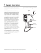
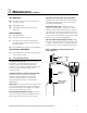
1 System Description The Manning EC-P2 is a portable, battery operated instrument for the measurement of gas concentrations in ambient air. Figure 1: Basic Parts of the Manning EC-P2 Sensor The Manning EC-P2 can be converted from one target gas to another by simply plugging in a different SMART-CELL for the desired target gas (takes about 30 seconds). This allows one instrument to detect a number of different gases.
1 System Description continued System Specifications Primary Power: Alkaline C cell battery, 48 hours operation. Note: An audible alarm single beep every 60 seconds indicates that either the Alkaline C cell battery is low or the internal rechargeable NiCad battery is low. Standby Power: Internal rechargeable NiCad battery, 6 hours operation. Note: An audible alarm single beep every 60 seconds indicates that either the Alkaline C cell battery is low or the internal rechargeable NiCad battery is low.
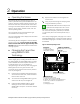
2 A Operation Operating the Sensor The Manning EC-P2 is shipped ready for use. To power up the instrument, push the PWR button. The power up sequence displays first the self check, the sensor full scale value, the downscale caution level, warning concentration setpoint, alarm concentration setpoint, output ranges, software version, then the normal operating screen. The unit will then display the instantaneous gas concentration and is ready for use.
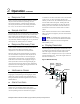
2 C Operation continued Response Test Prior to use, the unit should first be tested for proper response. With the detector operating, the unit should be exposed to a sample of the target gas. The display should show an increasing concentration. If not, do not use it for field measurements. D Sample Inlet Port The Manning EC-P2 is provided with a quick disconnect flexible extension wand. It will work with or without the wand. When using the extension wand, the internal walls must be kept dry.
3 A Maintenance Periodic Maintenance It is essential that the test and calibration schedule be adhered to. Honeywell Analytics recommends the following maintenance schedule: • Response test prior to each use. Expose sensor to a sample of the target gas to verify proper sensor response and alarm functions. • Calibration should be performed with certified calibration gas every six months, and all tests must be logged. • Check filter material every six months. Replace if dirty or moist.
3 Maintenance continued Zero Calibration 4) Be sure the unit is in clean air or apply zero air for two minutes. 5) Push ZERO button. 6) Push SAVE button to save the new zero calibration. Span Calibration 7) Push SPAN button. 8) Apply span gas for two minutes. 9) Push INC button (increase) or DEC button (decrease) until the display matches the span gas concentration. 10) Push SAVE button to store new span calibration.
4 A Programming and Advanced Features Alarm Setpoints, Functions The Manning EC-P2 has three adjustable alarm setpoints. These setpoints are stored on each SMART-CELL. The Caution setpoint is to warn of excessive negative zero drift. The WARNING and ALARM setpoints are to warn of potentially dangerous target gas concentrations. The following procedure will change the WARNING setpoint. To Enter CAUT / WARN / ALRM Mode 1) Push power button to turn unit on.
4 B Programming and Advanced Features continued Display Variables The Manning EC-P2 has two adjustable display variables. These variables control signal conditioning of the LCD display. Variables are stored on each SMART-CELL. The AVG (Average) variable determines the number of one second samples to average to calculate the displayed value. The lower the averaging value, the faster the display will change and the more “wiggle” will be displayed.
4 Programming and Advanced Features continued Programming sample mode variables: EC-P2 software installation: The sample mode variables are Sample, Measure and Clear as described above. The following procedure will change the Sample variable. The Manning EC-P2 is supplied with a CD containing the “Manning EC-P2” program. It will run on Windows 95, Windows 98, or Windows 2000. To install the program, place the disk in your CD drive. The CD should automatically begin the installation process.
4 Programming and Advanced Features continued Analog Output To Stop the Data Logging Session E 7) Push the MENU button. 8) Push the LOG button. 9) Push and hold the STOP button until the screen changes to CLEAR / INT / START / MODE (two seconds). 10) Push the DONE button to get back into normal operation mode. The Manning EC-P2 has a 0 to 1.0 volt DC analog output capability when used with the optional analog output cable.
5 Appendices APPENDIX A: SMART-CELLs Available GAS RANGE PART NUMBER Alcohol 0-500 ppm EC-P2-SMART-CELL-OH-0/500ppm Ammonia 0-500 ppm EC-P2-SMART-CELL-NH3-0/500ppm Ammonia 0-2000 ppm EC-P2-SMART-CELL-NH3-0/2000ppm Bromine 0-5 ppm EC-P2-SMART-CELL-Br2-0/5ppm Carbon Monoxide 0-1000 ppm EC-P2-SMART-CELL-CO-0/1000ppm Chlorine 0-5 ppm EC-P2-SMART-CELL-Cl2-0/5ppm Chlorine 0-200 ppm EC-P2-SMART-CELL-Cl2-0/200ppm Chlorine Dioxide 0-5 ppm EC-P2-SMART-CELL-ClO2-0/5ppm Flourine 0-5 ppm E
5 Appendices continued APPENDIX B: SMART-CELL Cross-Sensitivity Table (Interference Gases) SENSOR AND TARGET GAS I N T E R F E R E N C E G A S E S Bromine Chlorine Chlorine dioxide Ozone Ammonia Carbon monoxide Hydrogen Oxygen Nitrogen oxide Hydrogen sulfide Nitrogen dioxide Sulfur dioxide Formaldehyde Alcohol Flourine Hydrochloric acidNone Hydrogen peroxide Hydrogen cyanide Hydroflouric acid Hydride Silica hydride Carbon dioxide Methane Carbosulfonic acid Ethylene Ethyl alcohol Br2 ----1.0 1.0 1.
6 1. 2. Limited Warranty Limited Warranty Honeywell Analytics, Inc.