
EIM Installation Guide 2012


6
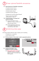
Typical wiring of a conventional system with up to 3-stage heat and 2-stage cool with
one transformer.
NOTE: See following pages for additional thermostat wiring guidelines for heat
pumps, geothermal systems and optional Economizer.
See guides on following pages for thermostat wiring and geothermal radiant heat
wiring.
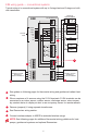
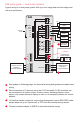
Wire a maximum of 4 sensors using the S1-S4 terminals. S1-S4 terminals can be
connected to an indoor sensor, outdoor sensor, discharge sensor, return sensor,
dry contact device to display an alert or an occupancy sensor for remote setback.
Remove jumper(s) if using separate transformers.
See Economizer wiring section.
HEAT STAGE 1
HEAT STAGE 2
HEAT STAGE 3
FAN
TO THERMOSTAT
STATUS
LEDS
JUMPERS
SENSORS
CONV
FURNACE
R
C
W
W2
W3
G
Y2
Y
TRANSFORMER
120
VAC
24
VAC
COMPRESSOR
STAGE 1
COMPRESSOR
STAGE 2
POWER
HEAT
COOL
FAN
U1
U2
U3
A
CONNECT OPTIONAL
SENSORS TO
S1 AND S2 TERMINALS
S4
S4
S3
S3
CONNECT OPTIONAL
SENSORS TO
S3 AND S4 TERMINALS
A
B
C
D
EIM
2
3
1
4
2
5
EIM wiring guide — conventional systems
1
2
3
4
Connect wireless adapter to ABCD for extended wireless range.
5