
Installation Manual


3
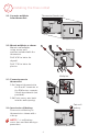
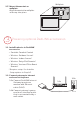
NOTE: If an EIM is mounted inside a metal cabinet, it is recommended to
use a THM4000R1000 Wireless Adapter for extended wireless range. Mount
the Wireless Adapter outside the metal cabinet and connect to the ABCD
terminals at the EIM.
NOTE: When installing multiple
thermostats and EIMs, mount
the EIMs at least 2 feet apart for
best RedLINK performance.
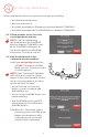
1.1 Mount EIM.
Mount the EIM near the HVAC
equipment or on the equipment
itself.
Use screws and anchors as
appropriate for the mounting
surface.
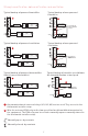
1.2 Wire EIM as shown.
Refer to the table and wiring diagrams on pages 35.
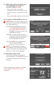
NOTE: If you are installing discharge and return air sensors, refer to the
mounting instructions in the Alerts and Delta T Diagnostics Installation
Instructions packed in the kit.
1
Installing the equipment interface module (EIM)
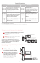
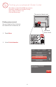
Terminal Designations
Conventional System Heat Pump
Terminal Description Terminal Description
C
Common wire from 24 VAC
transformer.
C
Common wire from 24 VAC
transformer.
R*
Power wire from 24 VAC
transformer.
R
Power wire from 24 VAC
transformer.
RH* Heating power. RH Heating power.
RC* Cooling power. RC Cooling power.
W Heat Stage 1 O/B Changeover valve for heat pumps.
W2 Heat Stage 2 AUX 1
Backup Heat Stage 1/Emergency
Heat Stage 1
W3 Heat Stage 3 AUX 2
Backup Heat Stage 2/Emergency
Heat Stage 2
Y Compressor Stage 1 Y Compressor Stage 1
Y2 Compressor Stage 2 Y2 Compressor Stage 2
G Fan Relay G Fan Relay
A
Connect to Economizer Module or
Lighting Panel (TOD).
L/A
Connect to Compressor Monitor,
Zone Panel, Economizer Module
or Lighting Panel (TOD).
* Remove jumpers when separate transformers are used.
R
C
Y
Y2
G
W
O/B
W2
AUX1
W3
AUX2
A
L/A