
THX9321 & THX9421 Product Data

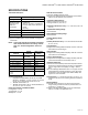
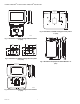
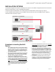
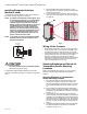
Table Of Contents
- Application
- Features
- Contents
- Specifications
- System Installation
- Installation Options
- Guidelines for Installing RedLINK Devices
- Installing Equipment Interface Module (if used)
- Wiring 24 Vac Common
- Selecting Discharge and Return Air Temperature Sensor Mounting Locations
- Selecting Return Air Temperature Sensor Mounting Location
- Installing Discharge and Return Air Temperature Sensors
- Selecting Thermostat Location
- Installing Wallplate
- Power Optional REDLINK™ Accessories
- Performing Initial Setup
- Linking Thermostat to Equipment Interface Module (if used)
- Linking RedLINK™ Accessories
- Completing Initial Setup
- Adding RedLINK Accessories to the Thermostat
- Locating the Connect Buttons on RedLINK Accessories
- Finding Your Password (Date Code) to Access Installer Options
- Installer Options
- Making Changes to Installer Setup
- Installer Tests
- Operation
- Setting the time/date
- Setting the fan
- Setting system mode
- Preset Energy-Saving Schedules
- Adjusting program schedules
- Overriding schedules: residential use
- Overriding schedules: commercial use
- Viewing equipment status
- Setting vacation hold: residential use
- Setting holiday/event schedules: commercial use
- Setting custom events: commercial use
- Setting holiday schedule: commercial use
- Setting holiday override: commercial use
- Initiating occupancy mode: commercial use
- Remote setback: commercial use
- Adjusting humidification settings
- Adjusting dehumidification settings: residential use
- Adjusting dehumidification settings: commercial use
- Adjusting ventilation settings
- Customizing screen color
- Setting preferences
- Cleaning the thermostat screen
- Adjusting security settings
- Viewing dealer information
- Advanced Features
- Installer options
- Using the temperature display
- Using the humidity display
- Universal Outputs (U1, U2, U3)
- Universal Inputs (S1, S2, S3, S4)
- Alerts and Diagnostics
- Heat Pump and Backup Heat Operation
- Indoor Air Quality (IAQ) Control
- IAQ Reminders
- Customizable Reminders
- USB Port
- Commercial Features
- Overriding schedules: commercial use
- Setting holiday/event schedules: commercial use
- Setting custom events: commercial use
- Setting holiday schedule: commercial use
- Setting holiday override: commercial use
- Initiating occupancy mode: commercial use
- Ramp Rates
- Custom Names
- Remote Setback
- Economizer and Time of Day (TOD) Operation
- Pre-Occupancy Purge
- Battery Replacement
- Optional Accessories
- Portable Comfort Control
- Remote Indoor Sensors
- Backup Control
- Replacing a Thermostat
- Replacing an Equipment Interface Module
- Wiring
- EIM Wiring Diagrams
- THX9321 Thermostat Wiring Diagrams
- THX9321 Thermostat Wiring Diagrams Using Universal Relays to Control Heating or Cooling
- Wiring IAQ Equipment or a Heat/Cool Stage to the Universal Terminals
- Economizer Module Wiring Diagrams
- Wiring C7089U1006 Outdoor Sensor
- Wiring guide — Wired Indoor Sensors
- Zoning
- Troubleshooting
- Regulatory Information

THX9321 PRESTIGE
®
2.0 AND THX9421 PRESTIGE
®
IAQ WITH EIM
68-0311—02 10
Installing Equipment Interface
Module (if used)
If no Equipment Interface Module is used, skip to “Selecting
Thermostat Location” beginning on page 12.
NOTE: If an EIM is mounted inside a metal cabinet, such
as a commercial rooftop unit, it is recommended
to use a THM4000R1000 Wireless Adapter for
extended wireless range. Mount the Wireless
Adapter outside the metal cabinet and connect to
the ABCD terminals at the EIM. The Wireless
Adapter functions as a remote antenna for the
EIM. After it is wired to the EIM, it automatically
takes over as the antenna for RedLINK communi-
cation. For best RedLINK performance, avoid
mounting the Wireless Adapter above the roof
deck or outside the exterior walls.
NOTE: If you install more than one thermostat and EIM,
the EIMs must be at least 2 feet apart for best
RedLINK performance.
Fig. 8.
CAUTION
Electrical Hazard.
Can cause electrical shock or equipment damage.
Disconnect power before wiring.
The Equipment Interface Module (EIM) can be mounted
vertically on the HVAC equipment or on a wall in the equipment
room.
1. Mount the EIM near the HVAC equipment or on the
equipment itself. Use screws and anchors as appropriate
for the mounting surface..
2. To wire the EIM, strip 1/4” insulation, then insert wires
(see Fig. 9). For wiring diagrams, see “Wiring” beginning
on page 135.
Fig. 9.
Wiring 24 Vac Common
• Single-Transformer System—Connect the common side of
the transformer to the C screw terminal of the EIM. Leave
the metal jumper wires in place between R, RC, and RH.
• Two-Transformer System—Connect the common side of the
cooling transformer to the C screw terminal of the EIM.
Remove the metal jumper wire between RC and RH.
Connect the hot side of heating transformer to RH and leave
the jumper wire between R and RC and connect the hot
side of cooling transformer to R or RC.
Selecting Discharge and Return Air
Temperature Sensor Mounting
Locations
Refer to the guidelines below and Fig. 10–14 for mounting
locations of the Discharge and Return Air Temperature
Sensors.
Selecting Discharge Air Temperature
Sensor Mounting Location
1. Mount the Discharge Air Temperature Sensor on the
supply duct in a location where the air is mixed well.
Mount the Discharge Air Temperature Sensor out of sight
of the A-Coil/Heat Exchanger when possible. See Fig.
10.
2. When possible, mount the Discharge Air Temperature
Sensor upstream of a Steam Humidifier, a Fan Powered
Humidifier or a Dehumidifier that is ducted to the supply.
See Fig. 11–12.
3. If space does not allow a Discharge Air Temperature
Sensor upstream of a Steam Humidifier or Fan Powered
Humidifier, mount the Discharge Air Temperature Sensor
downstream of the Humidifier. See Fig. 11. When setting
the Delta T Limits (see “Set Delta T Limits” on page 90),
be sure to consider the affect that the humidifier has on
Delta T.
4. If a Bypass Humidifier is installed, mount the Discharge
Air Temperature Sensor downstream of the Bypass
Humidifier. See Fig. 13–14.
EIM
A
B
C
D
WIRELESS
ADAPTER
CONNECT
POWER
THM4000R
CONNECTED
WIRELESS SETUP
MCR32389
R
C
Y
Y2
G
L
W
O/B
W2
AUX1
W3
AUX2