
THX9321 & THX9421 Product Data

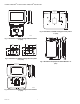
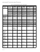
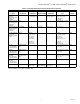
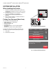
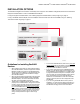
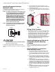
Table Of Contents
- Application
- Features
- Contents
- Specifications
- System Installation
- Installation Options
- Guidelines for Installing RedLINK Devices
- Installing Equipment Interface Module (if used)
- Wiring 24 Vac Common
- Selecting Discharge and Return Air Temperature Sensor Mounting Locations
- Selecting Return Air Temperature Sensor Mounting Location
- Installing Discharge and Return Air Temperature Sensors
- Selecting Thermostat Location
- Installing Wallplate
- Power Optional REDLINK™ Accessories
- Performing Initial Setup
- Linking Thermostat to Equipment Interface Module (if used)
- Linking RedLINK™ Accessories
- Completing Initial Setup
- Adding RedLINK Accessories to the Thermostat
- Locating the Connect Buttons on RedLINK Accessories
- Finding Your Password (Date Code) to Access Installer Options
- Installer Options
- Making Changes to Installer Setup
- Installer Tests
- Operation
- Setting the time/date
- Setting the fan
- Setting system mode
- Preset Energy-Saving Schedules
- Adjusting program schedules
- Overriding schedules: residential use
- Overriding schedules: commercial use
- Viewing equipment status
- Setting vacation hold: residential use
- Setting holiday/event schedules: commercial use
- Setting custom events: commercial use
- Setting holiday schedule: commercial use
- Setting holiday override: commercial use
- Initiating occupancy mode: commercial use
- Remote setback: commercial use
- Adjusting humidification settings
- Adjusting dehumidification settings: residential use
- Adjusting dehumidification settings: commercial use
- Adjusting ventilation settings
- Customizing screen color
- Setting preferences
- Cleaning the thermostat screen
- Adjusting security settings
- Viewing dealer information
- Advanced Features
- Installer options
- Using the temperature display
- Using the humidity display
- Universal Outputs (U1, U2, U3)
- Universal Inputs (S1, S2, S3, S4)
- Alerts and Diagnostics
- Heat Pump and Backup Heat Operation
- Indoor Air Quality (IAQ) Control
- IAQ Reminders
- Customizable Reminders
- USB Port
- Commercial Features
- Overriding schedules: commercial use
- Setting holiday/event schedules: commercial use
- Setting custom events: commercial use
- Setting holiday schedule: commercial use
- Setting holiday override: commercial use
- Initiating occupancy mode: commercial use
- Ramp Rates
- Custom Names
- Remote Setback
- Economizer and Time of Day (TOD) Operation
- Pre-Occupancy Purge
- Battery Replacement
- Optional Accessories
- Portable Comfort Control
- Remote Indoor Sensors
- Backup Control
- Replacing a Thermostat
- Replacing an Equipment Interface Module
- Wiring
- EIM Wiring Diagrams
- THX9321 Thermostat Wiring Diagrams
- THX9321 Thermostat Wiring Diagrams Using Universal Relays to Control Heating or Cooling
- Wiring IAQ Equipment or a Heat/Cool Stage to the Universal Terminals
- Economizer Module Wiring Diagrams
- Wiring C7089U1006 Outdoor Sensor
- Wiring guide — Wired Indoor Sensors
- Zoning
- Troubleshooting
- Regulatory Information

THX9321 PRESTIGE
®
2.0 AND THX9421 PRESTIGE
®
IAQ WITH EIM
9 68-0311—02
INSTALLATION OPTIONS
The THX9321 Prestige
®
2.0 thermostat is wired directly to the equipment. The THX9421 Prestige
®
IAQ thermostat is used with the
Equipment Interface Module or with a TrueZONE Wireless Adapter.
If using the Equipment Interface Module, see “Installing Equipment Interface Module (if used)” beginning on page 10.
If using a TrueZONE wireless adapter, follow the installation instructions that came with the TrueZONE, and go to “Selecting
Thermostat Location” beginning on page 12.
Guidelines for Installing RedLINK
Devices
— When installing more than one Thermostat and Equip-
ment Interface Module, mount the Equipment Interface
Modules at least 2 feet apart for best RedLINK perfor-
mance. No minimum distance is required between the
Thermostats if the Thermostat is linked to an Equip-
ment Interface Module.
— When the Thermostat is wired directly to the equipment
(No Equipment Interface Module and No TrueZONE
Wireless Adapter), mount the Thermostats at least 2
feet apart for best RedLINK performance.
— To determine if a RedLINK device will communicate
properly in the installed location, during the connection
process, press and quickly release the connect button
on the RedLINK device at the desired mounting loca-
tion. If the RedLINK device connects, then it will work
reliably during normal operation. If the RedLINK device
does NOT connect, try a new location. During the con-
nection process, the signal is sent at low power and
during normal operation the signal is sent at high
power.
— To connect a RedLINK device, make sure to press and
quickly release the connect button on the RedLINK
device. Press and holding the connect button down too
long will not allow the device to connect.
— If you link the Thermostat to the TrueZONE Wireless
Adapter, you will NOT be able to do the following: con-
trol humidification, dehumidification or ventilation, setup
a program schedule remotely from a computer, smart
phone or tablet, work with the Wireless Indoor Sensor,
Entry / Exit Remote or the Vent and Filter Boost
Remote. To use these features, wire the Thermostat
directly to the zone panel or use an Equipment Inter-
face Module.
— If you are using a RedLINK device from a previous
installation, you must reset the device first before you
re-connect it to the new Thermostat/Equipment Inter-
face Module. See page 134 for more information.
TM
TM
OR
THX9421 THERMOSTAT –
2 WIRES FOR POWER
RedLINK TO EQUIPMENT INTERFACE MODULE
RedLINK TO TrueZONE WIRELESS ADAPTER
THX9421 THERMOSTAT –
2 WIRES FOR POWER
THX9321 THERMOSTAT
WIRED DIRECTLY TO EQUIPMENT
OR
MCR34631
W
I
R
E
D
D
I
R
E
C
T
L
Y
T
O
E