
ZD Series Dampers Product Data
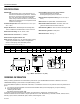
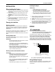

Table Of Contents

68-0247-2 G.H. Rev. 02-03 www.honeywell.com/yourhome
Automation and Control Solutions
Honeywell International Inc. Honeywell Limited-Honeywell Limitée
1985 Douglas Drive North 35 Dynamic Drive
Golden Valley, MN 55422 Scarborough, Ontario
M1V 4Z9
Printed in U.S.A. on recycled
paper containing at least 10%
post-consumer paper fibers.
Wiring a Motor
See Fig. 2 for typical motor wiring hookup.
Changing a Motor
1. Disconnect the motor wiring.
2. Loosen the large Allen set screw located between the
faceplate and the motor coupling.
3. Remove the motor.
4. Ensure damper blades are in the open position with the
set screw pointing toward the open position on the label.
5. Attach new motor to the coupling; be sure that the
standoff on the motor is positioned in the grommet on
the faceplate and that the set screw is aligned with the
motor shaft hole.
6. Tighten the set screw.
Adjusting a Motor
1. When viewed on end, the lower lever is normally posi-
tioned to the extreme left and the upper lever positioned
to the extreme right. See Fig. 4. This position provides
complete shutoff when the actuator is energized.
2. To prevent complete closure of the damper, loosen (do
not remove) the wing nut on the bottom of the unit and
move the upper lever to the left until the desired position
is reached. Tighten the wing nut. In the extreme left
position, the damper should stay open approximately
40° with the power on.
3. The lower lever is normally positioned to the left to allow
the damper to fully open 90° when energized. See
Fig. 4.
4. To restrict the air flow in the open position, loosen (do
not remove) the wing nut and move the lower lever to
the right until the desired position is reached. Tighten
the wing nut. In the extreme right position, the damper
should open approximately 50° with the power off.
Fig. 3. Air flow adjustment.
CHECKOUT
To check out the ZD:
1. With 24 Vac applied to the motor leads, observe the
motor powering the damper to the closed position.
2. When energized, verify that the actuator connection
coupling rotates in a clockwise direction (as viewed from
the operator base end) and that the damper shaft turns
with the coupling.
3. With power removed, observe the damper returning to
the normally-open position.
NOTE: To remove power, disconnect one wire from the
motor.
4. If the motor does not operate smoothly and without hes-
itation throughout the complete opening and closing
stroke, examine the damper and the shaft for free rota-
tion within the duct.
5. If the full opening and closing is not achieved, check
that the lower adjustment lever is to the extreme left and
the upper lever is to the extreme right. See Fig. 4.
UPPER LEVER
WING NUT
LOWER LEVER
M2015
5