
User's Manual


- Frequency counter more than 1000MHz +/-100Hz tolerance, high input impedance and high sensitivity
- UHF FM Signal generator, 1000MHz with adjustable frequency, FM deviation, and RF output attenuators.
50Ω Output impedance.
- Oscilloscope, high input impedance.
- 16Ω 1 Watt resistor as loudspeaker load
- Audio Signal Generator, 10Hz to 20KHz, 600Ω impedance with attentuators.
- RF Watt meter, with 50Ω 1 Watt termination resistor (Or RF Voltmeter with 50Ω termination and external
50Ω attenuators)
- Regulated Power Supply 4.6VDC 1A output
- Digital A-V-O Multi-meter
- SINAD Meter
- External Speaker Mic plug (or special audio test jig)
- Interconnection test cable for RF and Control PCB
- Circuit Diagram for GMRS X1
- PCB layout diagram for GMRS X1
- Tuning tools for RF/IF transformer and the VR potentiometers
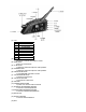
Transmitter Adjustment
- X-TAL frequency
On receiving mode, check X-TAL(X301)output (pin 2) is at 12.8MHz
VCO control voltage
Over 1V (RX), less than 3.3V (TX) On 1CH(462.5500MHz)
- Transmitter Frequency
Connect RF Power meter to ANT1, Activate PTT to transmit on Ch1 (462.5500MHz) check transmitting
frequency error is within +/- 250Hz. (adjust with VC301.)
- Transmitter Output Power
Activate PTT to transmit on CH1, Set adjust with VR201 for 2W power output at ANT1. Repeat test on Ch8.
- Transmitter Deviation Limit
Set radio to transmit on CH1, with CTCSS code 38 (250.3Hz) and no audio modulation. At the external
microphone input, inject 1KHz tone at –20dBm. Adjust VR501 for 2.0KHz deviation. Reduce 1KHz tone input
to –40dBm, check deviation dropped to 1.2 to 1.5KHz. Repeat test on Ch8.
Receiver Circuit Adjustment
- FM Demodulator Adjustment
Set radio to receive on Ch1, No CTCSS Connect RF Signal Generator to ANT1, Set generator to
462.5625MHz at –60dBm (50Ω) output with 1KHz tone modulation at 1.5KHz deviation
- Receiver Sensitivity
After adjusting the FM demodulator, reduce the output level of RF Signal Generator. Check the receiver
sensitivity at 12dB SINAD to be around –120dBm
- Receiver Squelch Adjustment
After checking the receiver sensitivity, further lower the RF Signal Generator output to 8-10dB SINAD and
observe the squelch circuit operates. Adjust VR401 if necessary.
5. Operational Test
Conduct operational test on all major features and transmit/receive on all the
channels. Observe all LCD displays and alert tones are operative and all the
buttons are functional. Refer to user manual for details.