User Guide AirPrime HL7588 TBC 1.
Contents 1. INTRODUCTION .......................................................................................................... 8 1.1. Common Flexible Form Factor (CF3) ................................................................................. 8 1.2. Physical Dimensions .......................................................................................................... 8 1.3. General Features ..............................................................................................
List of Tables Table 1. Supported Bands/Connectivity .......................................................................................... 8 Table 2. AirPrime HL7588 Features ................................................................................................ 9 Table 3. ESD Specifications ............................................................................................................. 13 Table 4. AirPrime HL7588 Environmental Specifications ...............................
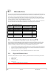
1. Introduction This document is the Product Technical Specification for the AirPrime HL7588 Embedded Module. It defines the high level product features and illustrates the interfaces for these features. This document is intended to cover the hardware aspects of the product, including electrical and mechanical. The AirPrime HL7588 belongs to the AirPrime HL Series from Essential Connectivity Module family.
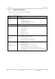
User Guide Introduction 1.3. General Features The table below summarizes the AirPrime HL7588 features. Table 2. AirPrime HL7588 Features Feature Physical Electrical RF SIM interface Application interface TBC Description Small form factor (146-pin solderable LGA pad) – 23mm x 22mm x 2.5mm (nominal) Complete body shielding RF connection pads (RF main interface) Baseband signals connection Single or double supply voltage (VBATT and VBATT_PA) – 3.2V – 4.
User Guide Feature Introduction Description Single mode LTE operation: LTE FDD, bandwidth 1.4-20 MHz System Release: 3GPP Rel.
User Guide Feature Introduction Description Multiple (up to 20) cellular packet data profiles Sleep mode for minimum idle power draw Mobile-originated PDP context activation / deactivation Support QoS profile Release 97 – Precedence Class, Reliability Class, Delay Class, Peak Throughput, Mean Throughput Release 99 QoS negotiation – Background, Interactive, and Streaming Static and Dynamic IP address.
User Guide 1.4. Introduction Architecture The figure below presents an overview of the AirPrime HL7588’s internal architecture and external interfaces. Figure 1. 1.5. AirPrime HL7588 Architecture Overview Interfaces The AirPrime HL7588 module provides the following interfaces and peripheral connectivity: TBC 1x - 4-pin UART 1x - Active Low RESET 1x - USB 2.0 1x - Backup Battery Interface 2x - System Clock Out 1x - Active Low POWER-ON 1x - 1.
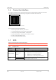
User Guide Introduction 1.6. Connection Interface The AirPrime HL7588 module is an LGA form factor device. All electrical and mechanical connections are made through the 146 Land Grid Array (LGA) pads on the bottom side of the PCB. Figure 2. AirPrime HL7588 Mechanical Overview The 146 pads have the following distribution: 66 inner signal pads, 1x0.5mm, pitch 0.8mm 1 reserved test point (do not connect), 1.0mm diameter 7 test point (JTAG), 0.8mm diameter, 1.
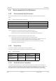
User Guide Introduction 1.8. Environmental & Certifications 1.8.1. Environmental Specifications The environmental specification for both operating and storage conditions are defined in the table below. Table 4.
User Guide 1.8.4. Introduction Disposing of the Product This electronic product is subject to the EU Directive 2012/19/EU for Waste Electrical and Electronic Equipment (WEEE). As such, this product must not be disposed of at a municipal waste collection point. Please refer to local regulations for directions on how to dispose of this product in an environmental friendly manner. 1.8.5.
2. Detailed Interface Specifications Note: If not specified, all electrical values are given for VBATT=3.7V and an operating temperature of 25°C. For standard applications, VBATT and VBATT_PA must be tied externally to the same power supply. For some specific applications, AirPrime HL7588 modules support separate VBATT and VBATT_PA connection if requirements below are fulfilled. 2.1. Power Supply The AirPrime HL7588 module is supplied through the VBATT signal with the following characteristics.
User Guide Detailed Interface Specifications Parameter LTE in communication mode (TX Max) HSPA+ (TX Max) 2.3.
3. FCC Regulations FCC Caution: Any changes or modifications not expressly approved by the party responsible for compliance could void the user's authority to operate this equipment. IMPORTANT NOTE – FCC Radiation Exposure Statement: This equipment complies with FCC radiation exposure limits set forth for an uncontrolled environment. This equipment should be installed and operated with minimum distance 20cm between the radiator & your body.
User Guide FCC Regulations If a multi-layered PCB is used, the RF path on the board must not cross any signal (digital, analog or supply). If necessary, use StripLine structure and route the digital line(s) "outside" the RF structure. An example of proper routing is shown in the figure below. Stripline and Coplanar design requires having a correct ground plane at both sides. Consequently, it is necessary to add some vias along the RF path.
User Guide Note: TBC FCC Regulations If this module is intended for use in a portable device, you are responsible for separate approval to satisfy the SAR requirements of FCC Part 2.1093. Rev 1.
4.
User Guide Abbreviation Terms and Abbreviations Definition QZSS Quasi-Zenith Satellite System RF Radio Frequency RFI Radio Frequency Interference RMS Root Mean Square RST ReSeT RTC Real Time Clock RX Receive SCL Serial CLock SDA Serial DAta SIM Subscriber Identification Module SMD Surface Mounted Device/Design SPI Serial Peripheral Interface SW SoftWare PSRAM Pseudo Static RAM TBC To Be Confirmed TBD To Be Defined TP Test Point TX Transmit TYP TYPical UART Universa