
User's Guide


TBC Rev 1.0 July 28, 2015 16
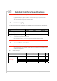
2.
Detailed Interface Specifications
Note:
If not specified, all electrical values are given for VBATT=3.7V and an operating temperature of
25°C.
For standard applications, VBATT and VBATT_PA must be tied externally to the same power
supply. For some specific applications, AirPrime HL7588 modules support separate VBATT and
VBATT_PA connection if requirements below are fulfilled.
2.1.
Power Supply
The AirPrime HL7588 module is supplied through the VBATT signal with the following characteristics.
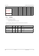
Table 6. Power Supply
Supply Minimum Typical Maximum
VBATT voltage (V)
3.2
1
3.7 4.5
VBATT_PA voltage (V) Full Specification
3.2
1
3.7 4.5
VBATT_PA voltage (V) Extended Range 2.8 3.7 4.5
1 This value has to be guaranteed during the burst.
Note:
Load capacitance for VBATT is around 32µF ± 20% embedded inside the module.
Load capacitance for VBATT_PA is around 10µF ± 20% embedded inside the module.
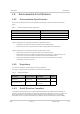
2.2.
Current Consumption
The following table lists the current consumption of the AirPrime HL7588 at different conditions.
Note:
Typical values are defined for VBATT/VBATT_PA at 3.7V and 25°C, for 50Ω impedance at all RF
ports. Maximum values are provided for VSWR4:1 with worst conditions among supported ranges
of voltages and temperature.
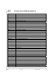
Table 7. Current Consumption
Parameter Minimum Typical Maximum Unit
Off mode 95.0 110 202.0 µA
Sleep mode – LTE
DRX = 1.28s
USB = suspended
Band 2 1.2 1.4 6.2 mA
Band 4 1.2 1.4 6.2 mA
Band 5 1.2 1.4 6.2 mA
Band 13 1.2 1.4 6.2
Band 17 1.2 1.4 6.2 mA