
User's Manual

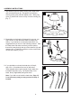

FAN AND LIGHT CONTROLLED BY REMOTE CONTROL
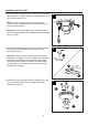
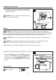
1. Connect BLACK wire from fan to BLACK wire from
ceiling. Connect WHITE wire from fan to WHITE wire
from ceiling. Connect all GROUND (GREEN) wires
together from fan to BARE/GREEN wire from ceiling.
[Fig. 1]
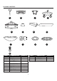
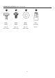
Hardware Used
Ball
C
B
A
REMOTE CONTROL
10
ASSEMBLY INSTRUCTIONS
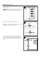
10. Install ball end of downrod (A) into mounting bracket
(C) opening. Align slot in ball with tab in mounting
bracket (C). [Fig. 10]
DANGER: Failure to align slot in ball with tab may
result in serious injury or death.
10
1
WIRING
WARNING7RUHGXFHWKHULVNRI¿UHHOHFWULFDOVKRFNRUSHUVRQDOLQMXU\ZLUHFRQQHFWRUV
provided with this fan are designed to accept only one 12-guage house wire and two lead wires from
the fan. If your house wire is larger then 12 guages there is more than one house wire to connect to
the two fan lead wires, consult an electrician for the proper size wire connectors to use.
CAUTION: Be sure outlet box is properly grounded or that a ground (green or base) wire is
present.
WARNING: if house wires are different colors than refereed to in the following step, stop
immediately. A professional electrician is recommended to determine wiring.
Note: Please refer to installation and operating instructions for remote control.
DD
Wire connector x 4