
User's Manual


H
G
AA
L
E
Screw
D
E
12
FINAL INSTALLATION
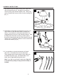
3. Insert two motor screws (AA), along with lock washers,
through one blade arm, (G) to attach blade arm, (G)
to motor. Tighten motor screws (AA) securely. [Fig.
3] Repeat with remaining blade arms (G), making
sure to completely secure each blade arm (G) before
proceeding with the next step.
4. Remove one of the four screws from the motor
assembly (E) and loosen the other three. Align the
screw holes of the light kit plate (L) with the loosened
screws and replace and tighten all screws.
3
4
AA
Motor Screw x 10
Hardware Used
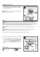
5. Remove one of the three screws from the light kit plate
(L) and loosen other two. Connect the connectors from
WKHOLJKWNLW¿WWHU'DQGIDQ$OLJQWKHVFUHZKROHV
RIWKHOLJKWNLW¿WWHU'ZLWKWKHORRVHQHGVFUHZVDQG
replace and tighten all screws.
5