SERVICE INSTRUCTIONS CARPET CLEANING MACHINE STEAM VAC Maytag Services 16025867
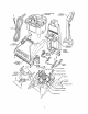
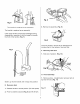
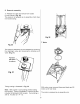
RECOVERYTANK HANDLE ASSEMBLY-'_ CORD ASSEMBLY RESERVOIR ASSEMBLY LOWER HANDLE ASSEMBLY HANDLE RELEASE LEVER '_ CARPET GROOMER BRUSH PUMP L.H. TRUNION DUC .
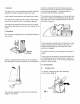
1. General The steam vac is a self contained designed for deep cleaning Initial models incorporate domestic extractor of carpet and rugs. six and seven amp motors. Top of the line models include a tool kit which allows the unit to be used for stair or upholstery cleaning. Suction is directed to the floor through the clear nozzle and up into the recovery tank where the air and water are separated. A float prevents the recovery tank from being overfitled.
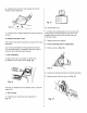
Replaceable components include the cap assembly, valve. of the tank assembly cap gasket and poppet SPRING-._/_ WASHERT_ B Cap assembly _' VALVE SEAL'_t_ 1. Twist off to remove. Fig. 3A (Fig. 2) VALVE STEM "'_ ._ The cupped end of the valve seal faces downward upon reassembly. To reassemble valve: 1. Slide valve assembly into valve seat through opening in bottom of tank. (Fig. 4) Use a small amount of soap on seal to case assembly. Fig. 2 2.
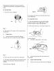
LATCH Fig. 8 Fig. 6 The. handle i.q r_.nlaep.d a._ an a._._.mhlv The handle is replaced 3. Remove lid assembly. (Fig. 9) as an assembly. If the upper handle rod becomes dislodged during disassembly, reposition it with the large fin towards the front of the handle. (Fig. 7) The lid is carried in service as an assembly that includes the lid, float retainer, float and filter. Fig. 7 F. Recovery tank duct 1. Slide out of position. (Fig. 10) FRONT PANEL Fig. _ LARGE FIN TOWARDS FRONT G.
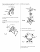
2. Carefully pry inward on rear panels of hood to release snaps. (Fig. 12) Fig. 15 Fig. 12 To reassemble 1. Lift hood until it clears latches and push forward to remove. H. Nozzle hood. 1. Position two locating tabs in front corners into mating boss on base and pivot hood down into position until the sides of the hoods snap into retaining bosses. front plate / seal 2. Replace screw and tighten. The nozzle front plate is stocked assembly. as a part of the hood K.
Pumpis replacedas an assemblywhich includesthe quickconnectandtubing.(Fig. 18) M. Motor cover assembly DISTRIBUTOR HOSE _ MOTOR COVER ASSEMBLY ® Fig. 18 The quick connect service item. is also available as a separate L. Pump duct The pump duct is held by the pump mounting (Fig. 19) Fig. 20 screw. 1. Disconnect 2. Remove hose to distributor. five screws (Fig. 21) and lift off. Fig. 19 On pump models, if pump is removed, five will already be out.
The motorcoverassemblyconsistsof the recovery tank latchesanddistributor. Handle release lever The RH trunnion traps the handle release lever. lever inward then up to remove. (Fig. 24) Slide _M \ ', \ To remove distributor. Fig. 24 1. Push outward on distributor stem while pulling out and down on 'T' boss. Distributor will snap out of housing. (Fig. 22) Switch N. Handle 1.
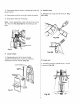
1. Disconnectleadsat switch,insulatedterminaland groundscrew. 2. Disconnectcordfromcordclip in backof handle. 0. Handle cover 1. Release four snaps and lift cover off. (Fig. 28 A & B) 3. Snapstrainreliefout of housing. Note: Uponreassembly,routecordas shownin Fig. 26. Also it is very important to reconnectground lead. \ Fig. 28A GROUND RELIEF Fig. 26 Fig. 28B P. Lower handle 1. Replaceable parts of the lower handle include the handle cover, lower rod, reservoir assembly and lower handle. (Fig.
S. Reservoir assembly t 1. Release two clips and remove from cradle in lower handle. (Fig. 30) The reservoir is replaced as an assembly which does not include tubing. \ Fig. 32 T. Motor The reservoir assembly can be inspected by removing the diaphragm valve and checking the chamber and valve. (Fig. 31) Pull here with to remove Fig. 31 Tubing routing is illustrated in Fig. 32. Note: 900 coupler in pump tubing protects tubing from kinking.
Note: Thefoam sealon the motorbaseis critical andmustbe replacedif damagedor missing. Positionthe foam per Fig. 33. Fig. 33 SEAL _ TANDPIPE Fig. 35 SEAL LOCATION 1. Remove of housing. Fig. 33 U. Motor 'E' clip and slide wheel shaft out (Fig. 36) seals MAIN BODY Two seals are positioned below the motor. (Fig. 34) "E" CLIP SHAFT Fig. 36 Fig. 34 Fig. 34 The seals can be removed position. V. Standpipe seal Press fit to standpipe. W. Rear wheel by prying them out of (Fig.
Hose assembly CONVERTER f HOSE WAND VALVE UPHOLSTERY Serviceable components of the hose assembly shown in the above diagram. are B. Upholstery nozzle Insert a screwdriver at the nozzle lock and pry upward on the flange on the upholstery nozzle. Pull the nozzle off the wand. (Fig. 38) A. Hose With a small screwdriver, push in on the hose bosses on both sides of the converter and wand valve assembly while pulling outward on hose. (Fig. 37) Fig. 38 Fig. 37 HOSE BOSSES Fig.
IV. Troubleshooting check list - Steam Vac The following is a guide to aid in determining the origin of a problem for which these models could conceivably be brought in for service. PROBLEM POSSIBLE CAUSE A. Motor won't run POSSIBLE SOLUTION 1. 2. 3. 4. 5. Unit not firmly plugged in. No voltage at wall plug. Open in attachment cord. Switch failed. Switch lever failed or out of position. . Crimp connections loose. 7. Open circuit in motor. 8. Motor brushes stuck or worn. 1. 2. 3. 4. 5. 6.
IV.Troubleshootingchecklist - SteamVac(cont'd) PROBLEMPOSSIBLE CAUSE D. Unit won't pump. (where applicable POSSIBLE SOLUTION 1. Solution tank empty. 2. Poppet valve malfunctioning. 1. Refill and check operation. 2. Check and replace - located in bottom of solution tank. 3. Clean and check operation. 4. Check and clean or replace. 5. Trace tubing and check for kinks - make sure 900 elbow is in place 6. Check to insure pump duct is secured. 7. Clean and check operation. 8.