NavMate® Navigation System Installation Manual Ver 1.
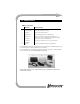
NavMate® Installation Manual 2 1.0 COMPONENTS TABLE 1. Components COMPONENT LOCATION/FUNCTION 1 Controller Mounts under a seat or in the trunk. 2 Controller Brackets Mounts the controller to the vehicle. 3 Display unit Mounts to the instrument panel. 4 Display Bracket* Mounts the display unit to the instrument panel. 5 GPS Antenna Mounts on top of the instrument panel, package shelf or outside. Please refer to “2) GPS antenna mounting” on page 6.
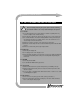
NavMate® Installation Manual 3 2.0 SAFTY INFORMATION AND PRECAUTIONS ! Before installing and using the system, please read the following precautions. Failure to do so may result in damage to the system. 2.1 Controller 1) Do not interrupt power to the system while the software is updating. This may result in corruption of the controller memory. 2) Never drop the controller. This may destroy the gyroscope or other components.
NavMate® Installation Manual 4 3.0 INSTALLATION 3.1 Determine system layout 1) Determine the location to connect to the vehicle speed signal. Please call 186NAVMATE1(1-866-286-2831) for VSS help. 2) Determine the location to connect to the remaining vehicle signals required by NavMate. Please refer to Table 2 on pag e5 for signal requirements and NavMate wire colors. 3) Determine general component layout, e.g., where the controller will be mounted. 3.
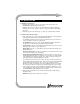
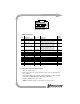
NavMate® Installation Manual 5 8 7 6 5 4 3 2 1 16 9 10 11 12 13 14 15 CONTROLLER CONNECTOR (WIRE HARNESS VIEW) TABLE 2. Signal/Power Typical location No. Signal/Power Wire Color Requirements 1 2 Ground (battery minus) Reverse gear signal Black Light Green Chassis Backup light 3 Ignition signal Pink 4 Vehicle speed signal (sine wave) Yellow 5 Vehicle speed signal (square wave) Green/White battery minus +13.8V DC nominal (when vehicle in reverse) Low level voltage VL max: 1.0 VL (min.
NavMate® Installation Manual 6 3.4 Mount components and tuck cables 1) Controller mounting Mount the controller to the vehicle using the brackets provided. The controller must be firmly attached to the vehicle for the system to function properly. Do not overtighten. Do not mount the controller upside down. The controller must be mounted level to within 5 degrees with the vehicle parked safely on reasonably level ground. Use a bubble level to verify.