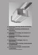
D Anleitung für Montage, Betrieb und Wartung Garagentor-Antrieb GB Installation, Operating and Maintenance Instructions Garage Door Operator F Instructions de montage, de manoeuvre et d’entretien Motorisation de porte de garage NL Handleiding voor montage, bediening en onderhoud Garagedeuraandrijving I Istruzioni per il montaggio, l'uso e la manutenzione Motorizzazione da garage E Instrucciones para el montaje, funcionamiento y mantenimiento Automatismo para puerta de garaje P Instruções de mon
Deutsch................................................................................. 3 English .................................................................................. 6 Français ................................................................................ 9 Nederlands ......................................................................... 12 Italiano ................................................................................ 15 Español ..............................................
ENGLISH TABLE OF CONTENTS PAGE A B Supplied items Required tools for installation 2 2 1 1.1 1.1.1 1.1.2 1.2 1.2.1 1.2.2 1.3 1.4 1.5 IMPORTANT NOTES Important safety instructions Warranty Checking the door / door system Important instructions for a safe installation Before installing the garage door operator Carrying out the installation work Warnings Maintenance advice Information on the illustrated section 7 7 7 7 7 7 8 8 8 8 Illustrated section 24-49 2 2.1 2.2 2.3 2.4 2.5 2.6 2.
ENGLISH Dear Customer, Thank you for choosing this quality product from our company. Please keep these instructions in a safe place for later reference. Please observe the following instructions. They provide you with important information on the safe installation, operation and correct care/maintenance of your garage door operator, thus ensuring that this product will give you satisfaction for many years to come.
ENGLISH 1.2.2 Carrying out the installation work 1.4 Maintenance advice The garage door operator is maintenance-free. For your own safety, however, we recommend having the door system checked by a specialist in accordance with the manufacturer’s specifications. Inspection and maintenance work may only be carried out by a specialist. In this connection, please contact your supplier. A visual inspection may be carried out by the owner. If repairs become necessary, please contact your supplier.
1.2.2 /2.2 1.1a 1a 30 1.4 a 1.2 a 1.5 a /1.6 a 1.4 a 1.2a 2.3 1.3 a 1.2 a 1.5 a /1.6 a 1.3 a 24 2.3 04.
15 1.4 a 04.
1.5 a 2.4 /2.5 B B B B B Ø B 5 EPU/LTE/ LPU/LTH 40 1.6 a Ø 10 ≥113 ≥138 A EPU/LTE/ LPU/LTH 40 Ø 10 60 55 A 26 > 55 ≥ 65 04.
1.1b 1b 1.2.2 / 2.2 1.5 b /1.6 b 30 1.2 b 1.3 b 1.4 b 1.2b 1.2 b 1.3 b 1.4 b 1.3 b 2.6 1.5 b 2.7 2.6 N 80 = 50 DF 98 = 85 1.4 b 2.6 B 5 1 / 2 1 / 2 Ø 04.
1.6 b 1/2 1/2 1/2 1/2 1/2 N 80 1/2 B 2.7 1/2 N 80 1/2 B Ø 10 1/2 DF 98 1/2 1/2 1/2 90 A Ø F 80 10 1/2 1/2 60 67 A 28 04.
2.9 2.1 2 2.10 2.1- 2.3 2.5 0 20 2.4 2.2 2.3 2.4 a D 2.4b 2.10 BR40 N/L/Z C 0 00 .3 ax m 0 25 x. a m 60 Ø 10 00 .6 ax m 00 .6 ax m A 2.5 G 2.10 A 04.
3a 3.1a 3.1a E E E E 30 04.
3b 3.1b 3.1b N 80 E E DF 98 E E 04.
4.1 2.11.1 4.2 2.11.1 5.1 2.12 5.2 2.12 10 32 6 2.11.2 04.
7 3.3 F ≥ 100 8 3.2 / 3.5 3.1 YE BN WH GN I2 22 24V 5 I1 21 0V 20 BUS X30 230-240 V 04.
9 3.2 min. 1 x 0,5 mm2 max. 1 x 2,5 mm2 3.6 10 + - + - 22 5 21 11.1 3.7 11 3.7.1 + - + - 22 5 21 11.2 3.7.2 12 3.8 11.3 3.7.3 0V 0V TX RX 0V TX 0V RX 22 34 04.
13 3.9 22 +24V 5 21 20 BUS 0V 5 3 1 4 3.10 14 22 + 24V 5 21 20 BUS 0V 15 5 2 1 4 3.11 HOR 1 22 HOR1 16 5 21 20 .8 .5 .6 X30 U 3.12 22 UAP1 04.
17 D GB F Hinweis In den Menüs werden die aktuellen Einstellungen durch einen leuchtenden Punkt dargestellt. NL Opmerking In de menu's worden de actuele instellingen door een lichtend punt weergegeven. Note In the menus the current settings are represented by a glowing decimal point. I Avvertenza Le impostazioni effettuate vengono rappresentate nei menu mediante un punto luminoso Remarque Dans les menus, les réglages en cours sont indiqués par un point lumineux.
20 4.5.1 4.5.1 04.
21 5 5.2 1x 12 Volt 23A 22.1 6.1.1 22.2 6.1.1 22.3 6.1.1 38 04.
22.5 6.1.4 30 0 6.1.3 50 22.4 16 16 04.
23.1 6.2.1 1 min. 2 min. 3 min. 4 min. 5 min. 23.2 6.2.2 5 min. 10 min. 15 min. 23.3 40 6.2.3 04.
D GB F NL 04.
7.3 24 0 sec. 10 sec. 7.2.1 20 sec. 30 sec. 45 sec. 7.2.2 60 sec. 90 sec. 120 sec. 150 sec. 180 sec. 42 04.
7.4 25 7.2.1 + 24V 5 19 0V 4 + 24V 5 19 18 4 7.4 7.2.2 0V + 24V 0V 04.2007 TR10A041-C RE 7.
5 – 7.5 26 .6 .5 .8 5 sec. 7.2.1 10 sec. 7.2.2 1 sec. 44 04.
7.6 27 7.2.1 7.2.2 7.6.1 04.
7.7 28 7.2.1 7.2.2 46 04.
7.8 29 7.2.1 7.2.2 7.8.1 04.
7.9 30 7.2.1 7.2.2 48 04.
7.10 31 7.2.1 7.2.2 32 4.6 33 11.1 04.
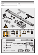
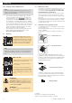
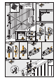
ENGLISH 2 INSTALLATION INSTRUCTIONS Note When drilling holes, cover the operator so as to avoid the penetration of dust and shavings, since these can lead to malfunctions. 2.1 Garage door operator 2.2 Required clearance for installing the operator When installing the operator the clearance between the door at its highest point of travel and the ceiling must be at least 30 mm (see fig. 1.1a/1.1b ). Please check these dimensions! 2.
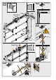
ENGLISH 2) Insert the limit stop for the CLOSE end-of-travel position loosely into the boom between the carriage and the drive unit. Push the door by hand into the CLOSE position. In this way the limit stop is pushed close to its correct position. When the CLOSE end-of-travel position has been reached, move the limit stop approx. 1 cm further towards the CLOSE position and then fix it in place (see fig. 5.2). 3.
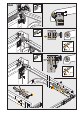
ENGLISH 4 PUTTING THE OPERATOR INTO SERVICE 4.1 General information The operator control contains 13 menus, via which the user can select numerous functions. To put the operator into service, however, only two menus are required: adjustment/setting of the door type (menu J) and learning the distance of travel (menu 1). distance of travel as well as the required force to open and close the door are learned and automatically stored. 4.5.
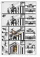
ENGLISH 2. 3. 4. 5. 2. Take a blunt object and gently press and hold button . Press and hold the PRG button Insert the mains plug Release the PRG button as soon as C is displayed Adjust and programme the operator Note: Do not use any sharp objects. Excessive pressure can destroy the button. Note The programmed radio codes (impulse / light / partial opening) are retained. 5 HAND TRANSMITTER (see fig. 21 ) 5.1 3. Press and hold the button that you wish to code.
ENGLISH Note If the same radio code is programmed for two different functions, the code for the function first programmed is deleted and the most recently programmed code remains valid. 6.1.2 Deleting all the radio codes of a function 1. Select menu P. 2. Select parameter 0, 1 or 2. 3. Press the PRG-button until the decimal points starts to flash. 4. Press OPEN button ( ) and CLOSE button ( ) simultaneously. 5.
ENGLISH Operator lighting by radio signal, external push-button the decimal point lights up. If the PRG button is released prematurely, this calls up the next menu. If no button is pressed and the operator has completed the learning process, the control system automatically returns to normal operation (menu 0). not active 5 minutes 7.2.
ENGLISH 7.4 MENU 4 – safety devices (see fig.
ENGLISH 7.7 MENU 7 – behaviour during operation in the CLOSE direction (see fig. 28 ) In this menu, the automatic belt relief, the braking behaviour and the speed in the CLOSE end-of-travel position can be influenced. Note After the menu changes, a learning cycle may have to be carried out. Display Soft stop Function 7.9 MENU 9 – behaviour during operation in the OPEN direction (see fig.
ENGLISH 7.10 MENU A – maximum force (see fig. 31 ) In this menu, the maximum force limit is set.
ENGLISH Universal fitting: For up-and-over and sectional doors Door speed: Depending on the door type, door size, door action and weight - closing: approx. 14 cm/s - opening: approx. 22 cm/s Air-borne noise of garage door operator: 11.1 ≤ 70 dB (A) Boom: Extremely flat (30 mm) with integrated door security kit and maintenance-free toothed belt. Application: Exclusively for garages in the domestic sector. Not suitable for industrial / commercial use.
ENGLISH 8 Error messages and warnings Note: In the event of an error or warning a number is displayed with a rapidly flashing decimal point.
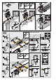
4.5.1 4.5.1 20 4.4 19 04.
130 6.1.1 6.1.1 6.1.1 22.2 22.3 1x 12 Volt 23A 5 22.1 21 5.2 22.5 22.4 6.1.4 6.1.3 16 16 50 04.2007 TR10A041-C RE 30 0 23.3 23.2 23.1 6.2.3 6.2.2 6.2.1 15 min. 10 min. 5 min. 5 min. 4 min. 3 min. 2 min. 1 min.
04.
04.