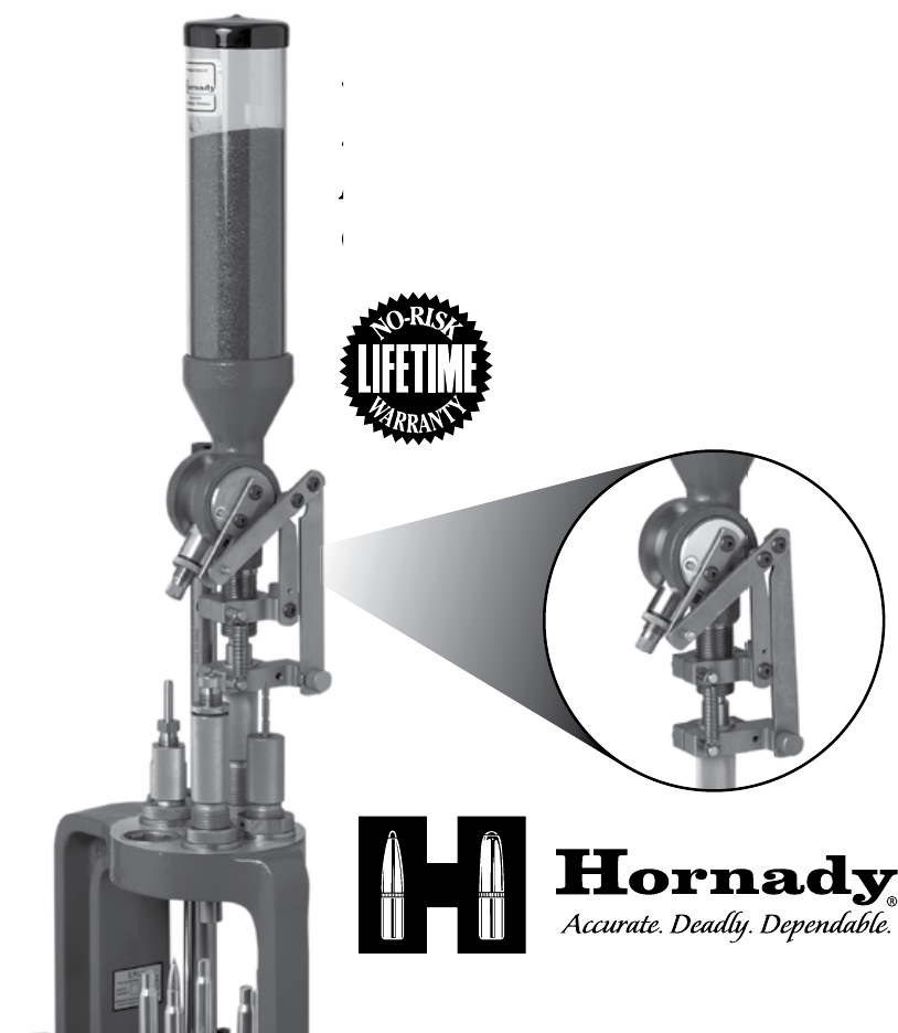
Lock-N-Load Lock-N-Loa ® Powder Measure and Case Activated Powder Drop
Table of Contents Chapter 1: Lock-N-Load Powder Measure Page 4 4 5 5 6 Overview Step 1: Disassemble Step 2: Assemble Step 3: Operate and Adjustment Step 4: Precautions Charts 1. Bill of Materials of Lock-N-Load Powder Measure 2.
Chapter 2: Case Activated Powder Drop Overview Step 1: Assembling the Case Activated Powder Drop Rotor Arm Step 2: Upper Bracket Assembly Step 3: Drop Tube Installation Step 4: Installing the Case Activated Powder Drop (Lower Assembly) Step 5: Final Powder Measure Assembly Step 6: Case Activated Powder Drop Adjustment Page 9 10 11 12 13 15 16 Figures 1. Attaching the Case Activated Powder Drop Rotor Arm 2. Upper Bracket Assembly 3. Drop Tube Installation 4.
ChapTer 1 Hornady Lock-N-Load Powder Measure Instructions -3-
Your Powder Measure has been treated with a rust preventative which must be removed before use. We recommend that you clean and degrease all metal parts with Hornady One-Shot Cleaner and Dry Lube. To Disassemble: Set the Rotor with the Metering Unit perpendicular to the axis of the Body, press the Push Button and hold it down while removing the Metering Unit. NOTE: Do NOT remove push button. It is permanently installed and does not need cleaning.
To Assemble: Reverse the procedure in the first five steps above. The Rotor and Body are very closely fit and must be properly aligned to reassemble. DO NOT FORCE IT OR IRREPAIRABLE DAMAGE WILL OCCUR. To Operate and Adjust: Attach the Mounting Bracket to your bench or shelf using (2) #14 Binding Head Sheet Metal Screws or other suitable hardware. The screws should be approximately _" back from the edge of the bench, and the smaller of the two large holes should be suspended off of the bench.
The Lock Nut and O-ring on the Metering Unit may be adjusted to provide tension on the thread of the Plunger, so as to allow setting it while not allowing unintentional movement in operation. It may be locked in place by tightening when adjustment is achieved. One revolution of the plunger is .05" travel. With the plunger all the way in, or the capacity set to near zero, the end of the thread and the outer surface of the Lock Nut should be approximately flush.
Bill of Materials Item No. Production Part Number Qty.
-8-
Chapter 2 Case Activated Powder Drop The Case Activated Powder Drop helps make reloading faster and easier than ever before. It automatically activates and dispenses a charge with every pull of the handle, but only when a case is present in the station. Plus, it works with Lock-NLoad bushings. (You can remove and change Hornady powder measures with a quick turn, without changing adjustments.) The Case Activated Powder Drop unit can be used ONLY on the Hornady Lock-N-Load Powder Measure.
L-N-L POWDER MEASURE Fig. 1: Attaching the Case Activated Powder Drop Rotor Arm. Step 1: Assembling the Case Activated Powder Drop Rotor Arm Reinstall the Rotor with the handle side to the right (metering opening facing you). Place the Metering Unit back into the Rotor. Attach the Case Activated Powder Drop Rotor Arm (#3) to the right side of the Rotor using two Button Head Cap Screws (#4).
Step 2: Upper Bracket Assembly Slide the Upper Bracket Assembly onto the Powder Measure. Engage Drive Link Pin (#10) into the Rotor Arm Slot. Adjust the position of the Upper Assembly so that the drive link pivot is across from the centerline. Tighten the two Button Head Cap Screws (#1) and (#9). The longest screw 10-32 X 1.25 goes in the front hole. Screw on the Spring Nut (#13) to the end of the 10-32 X 1.25 screw. Fig. 2: Upper Bracket Assembly.
Step 3: Drop Tube Installation Screw the Drop Tube (#16) into the bottom of the Powder Measure. Lubricate the exterior of the Drop Tube (#16) with Hornady One Shot Gun Cleaner and Dry Lube or other similar dry lubricant. Fig. 3: Drop Tube Installation.
Step 4: Installing the Case Activated Powder Drop (Lower Assembly) Screw the Measure Adapter (Lower Assembly) into the reloading press a couple of turns. Select the appropriate powder bushing sleeve for your application. (Each sleeve has a shallow countersink on one side, and a deep counter sink on the other.) Insert the bushing, with the deep counter sink facing up, into the top of the measure adapter.
Fig. 4: Installation for the Case Activated Powder Drop (Lower Assembly).
Step 5: Final Powder Measure Assembly Insert the Powder Drop Tube (#16) into the lower assembly. (Refer to pg. 13) Connect the slot on the Measure Link (#8), (Refer to pgs. 17 & 18 for more details). Fig. 5: Final Powder Measure Assembly.
Step 6: Case Activated Powder Drop Adjustments Insert a case into the shell plate at station 3 of your Lock-N-Load AP and operate the handle to raise the ram to its highest position. (refer to pg. 13 in your Lock-NLoad AP manual) Lower the Powder Measure by rotating it Clock-Wise (CW) into the press until the Powder Measure Rotor is fully rotated, but not contacting the end of the slot in the Powder Measure Body. Lower the Ram and attach the Return Spring (#14) between the two Spring Pins (#13).
BILL OF MATERIALs Item No. Production Part Number Qty. 1 392721 4 Description BHSCS 10-32 X 1.00 2 392708 2 MOUNTING CLAMP 3 392710 1 ROTOR ARM 4 392719 5 BHSCS 10-32 X 3/8 5 392715 2 SHOULDER NUT 6 398735 1 PIVOT 7 398737 1 DRIVE LINK 8 398736 1 MEASURE LINK 9 398742 2 BHSCS 10-32 X 1.
6 1 5 4 2 7 3 9 8 11 10 12 16* 4 13 17 18 19 15 14 1 9 20 22 23 2 21 13 24 25 26 - 18 -
P.O. Box 1848 • Grand Island, NE 68802-1848 (308) 382-1390 • www.hornady.