OWNER'S MANUAL LOCK-N-LOAD ® RIFLE BULLET FEEDER
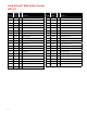
Lock-N-Load® Rifle Bullet Feeder PARTS LIST Production Item No. Part No. Qty. Description -2- Production Item No. Part No. Qty.
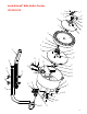
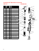
Lock-N-Load® Rifle Bullet Feeder EXPLODED VIEW 3 4 2 11 5 6 7 8 1 12 9 13 15 10 14 16 18 17 37 19 3 26 38 30 27 20 28 21 22 23 24 25 39 25 25 29 30 30 14 36 20 31 35 34 32 33 -3-
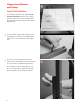
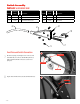
Hopper Installation and Setup 1 Support Tube Installation 1 Place the Hornady® Lock-N-Load® AP™ template (located in the back of the manual) on the table in the location you would like to mount the press and the Lock-N-Load® Rifle Bullet Feeder. Drill ¼" holes for the placement of the Bottom Support Tube (36). 2 Use ¼" bolts with ¼" flat washers (Not provided, due to the varying thicknesses of tables) on top of the Bottom Support Tube (36) and also one on the bottom of the bench. Tighten snug.
Hopper Installation 4 Slide the hopper onto the Top Support Tube (29), with the hopper opening facing the front of the bench. Place a ¼-20 x 2 SHCS Bolt (29) with one ¼" Flat Washer (30) through the middle and bottom holes of the Bullet Feed Hopper (29) and the Top Support Tube (37). 4 Nut Place a ¼" Flat Washer (30) then a ¼-20 Hex Nut (14) onto the end of each of the ¼-20 x 2 SHCS Bolts (29) and tighten snug.
Switch Assembly PARTS LIST & EXPLODED VIEW Production Item No. Part No. Production Item No. Part No. Qty. Description Qty.
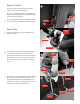
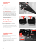
Hopper Testing 9 9 Plug in the Power Supply (34) and turn on the empty feeder using the 2 Position Switch (32). If the feeder doesn’t turn on, refer to 12A on the next page for adjustment procedure. Power Supply 2 Position Switch Turn off, then put approximately 100 bullets in the Feeder Bowl (24). Do not over fill. 10 Hold the Feed Tube (68) and turn on the Feeder using the 2 Position Switch (32). Catch the bullets as they fall and make sure all bullets feed base-first.
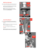
Switch Adjustment (if necessary) 12 B 12 12A: Hopper does not start If the hopper does not rotate, make sure the power supply is plugged in and the 2 Position Switch (32) is on. If it still does not rotate, loosen the screw shown in the image and slide DOWN slightly until a faint clicking of the switch can be heard. Re-tighten (slightly snug: do not over tighten). A 12B: Hopper does not stop If the hopper does not shut off, turn off the hopper with the 2 Position Switch (32) and empty the Feed Tube.
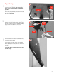
Bullet Drop Adjustment 15 15 Feed Tube Retainer Loosen the Lock Rings (44) and adjust the height of the Feed Tube Retainer (53) approximately 1/16" above the bullet tip. Lock Ring Adjust location of the Feed Tube Retainer (53) so the bullets drop freely into the Feeder Block (58 or 59). NOTE: If the bullets don’t drop freely, the Feed Support Bracket (54) can be slightly adjusted by loosening the Pan Head Screws (56). Refer to photo 16A.
Lock-N-Load® Rifle Bullet Feeder Die PARTS LIST Production Item No. Part No. - 10 - EXPLODED VIEW 40 53 Qty. Description 40 399327 1 Feeder Clamp, RBF 41 69006 1 Thumb Screw, 6-32 X .
Die Adjustment 17 Preparation 17 As with all dies, disassemble the die and clean thoroughly. Reassemble according to the illustration. Do not attach the Feeder Body (63). Set the distance between the Crimp Adjust Screw (46) and the Crimp Adjust Lock Ring (47) to 0.10" (about 2 turns back). The Crimp Adjust Lock Ring should have firm tension on the O-Ring (48) against the Die Body (51). Crimp Adjust Lock Ring Crimp Adjust .
Die Placement 19 19 With a chamfered case in the shell plate, raise the press ram to the top of its stroke. Screw the assembled die into the press until resistance is felt. This resistance is the case starting to crimp in the Alignment Sleeve (49). Back the die off approximately half of a turn. Die Body Alignment Sleeve 20 Screw the Sure-Loc® Lock Ring (52) down against the press or Lock-N-Load® Bushing and lock into place by tightening the cap screw.
22 Set the bullet seat depth by lowering the press ram, threading the Seat Adjust Screw (42) into the die and raising the press ram again until the desired seating depth/cartridge length is obtained. Make sure the Crimp Adjust Screw (46) does not move when adjusting the seating depth. 22 Seat Adjust Screw Crimp Adjust Screw Note: Do not, at this time, tighten the Seat Adjust Lock Ring (44).
Tune & Lock the Die Next, lower the press ram and remove the cartridge. Place the next set of components in the press and seat/crimp another round. 24 Feeder Clamp Thumb Screw Fine tune the crimp/seat depth if necessary. When adjusting the Crimp Adjust Screw (46), hold the Seat Adjust Screw (42). When adjusting the Seat Adjust Screw (42), hold the Crimp Adjust Screw (46). Doing this will allow the crimp amount to be adjusted without moving the seating depth and vice versa.
Load 26 26 Put a case in the shell holder and cycle the press ram. The bullet in the Alignment Sleeve (49) will seat into the case. Simultaneously the Feed Block (58 or 59) will rotate and drop a bullet. Note: The first stroke of the press will not seat a bullet if there isn't a bullet in the Alignment Sleeve (49). 27 When the ram is lowered, the bullet will slide down the Bullet Ramp (66), push aside the Seating Stem (43), and drop into the Alignment Sleeve (49).
Troubleshooting the Lock-N-Load®Rifle Bullet Feeder Problems Hopper does not turn on Possible Causes & Solutions • Switch cable is not connected to the micro switch. Connect the cable to the switch (see step 8). • Power supply is not plugged in. Plug in power supply (see step 9). • Power switch is not turned on. Turn on switch (see step 9). • Micro switch is out of adjustment. Adjust the switch (see step 12A). • Bullet or other object is stuck in the switch housing. Clear the obstruction.
APPENDIX B - TEMPLATE Lock-N-Load® AP™ APPENDIX B
680030 P.O. Box 1848, Grand Island, Nebraska 68802-1848 308-382-1390 • 800-338-3220 • Fax: 308-382-5761 www.hornady.com • webmaster@hornady.