User Manual for HE–QX351 / HEQX351C103 MAN0892-03-EN
MAN0892-03-EN PREFACE PREFACE This manual explains how to use the QX351 OCS Modules. Copyright (C) 2008 Horner APG, LLC, 59 South State Avenue, Indianapolis, Indiana 46201. All rights reserved.
MAN0892-03-EN PREFACE LIMITED WARRANTY AND LIMITATION OF LIABILITY Horner APG, LLC, ("HE-APG") warrants to the original purchaser that the QX351 OCS module manufactured by HEAPG is free from defects in material and workmanship under normal use and service.
MAN0892-03-EN PREFACE Table of Contents PREFACE.................................................................................................................................................. 3 For user manual updates, contact Technical Support:.............................................................................. 3 LIMITED WARRANTY AND LIMITATION OF LIABILITY ......................................................................... 4 ABOUT PROGRAMMING EXAMPLES...................................
MAN0892-03-EN PREFACE 7.4 Ethernet Module Configuration.................................................................................................... 31 CHAPTER 8: REMOVABLE MEDIA......................................................................................................... 35 8.1 Micro SD Overview ...................................................................................................................... 35 8.1.1 Accessing Files with an QX351 OCS.................................
MAN0892-03-EN PREFACE 17.1 Connecting to the QX351 .......................................................................................................... 103 17.1.1 Connecting Troubleshooting Checklist (Serial Port – MJ1/MJ2 Programming)......... 104 17.1.2 Connecting Troubleshooting Checklist (USB Port - Mini B Programming) ................ 104 17.1.3 Connecting Troubleshooting Checklist (Ethernet port Programming) ....................... 104 17.2 Local Controller and Local I/O ......................
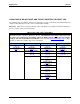
MAN0892-03-EN PREFACE VISUAL MAP OF MAJOR TASKS AND THE KEY CHAPTERS TO ASSIST YOU The following map is provided to show you the major types of tasks needed to be performed and the key chapters in this manual you need to refer to for information and help. Directions: Major tasks are listed at the top of the map with the key chapters listed beneath that you need to consult in order to perform the tasks. FIRST STEP of ANY TASK: DATASHEET Each QX351 unit is sent with a datasheet in the box.
MAN0892-03-EN CH.1 CHAPTER 1: SAFETY / COMPLIANCE 1.1 Safety Warnings and Guidelines When found on the product, the following symbols specify: Warning: Consult user documentation. Warning: Electrical Shock Hazard. WARNING – EXPLOSION HAZARD: Do not disconnect equipment unless power has been switched off or the area is known to be non-hazardous WARNING: To avoid the risk of electric shock or burns, always connect the safety (or earth) ground before making any other connections.
CH.1 • • 1.2 MAN0892-03-EN Make sure the unit is turned OFF before making connection to terminals. Make sure all circuits are de-energized before making connections. Before each use, inspect all cables for breaks or cracks in the insulation. Replace immediately if defective. Grounding Grounding is covered in various chapters within this manual. • • 1.3 For grounding specifications and testing for a good ground, refer to section 4.2 For Panel grounding, refer to section 4.
MAN0892-03-EN CH.2 CHAPTER 2: INTRODUCTION 2.1 Visual Overview The QX351 OCS provides flexible options allowing you to choose the functionality you need. A QX Base unit can be used alone.
CH.
MAN0892-03-EN CH.2 Battery Cover Ethernet USB A FOX I/O Bottom Side Power CAN MJ1 MJ2 DIP Switches Left Side Figure 2.1: Visual Overview of QX351 QX Base Model QX351 February 25, 2010 Network On-Board Ethernet 100BaseT Screen Type 5.
CH. 2 MAN0892-03-EN Plastic SmartStack Provide a wide variety of I/O options for the QX. Require little space and are easy to Modules install. QX351 supports upto 2 smartstack modules. Fiber Optic Extension Extends a high-speed QX backplane enabling SmartStack I/O Modules to be mounted System (FOX) several meters from the QX. The FOX, also, significantly increases the number of SmartStack I/O modules supported by one QX. SmartStix Modules It is a family of remote I/O products for the QX. 2.1.
MAN0892-03-EN • • • • • • • • • • • • b. CH.2 Bright, 32000 Color graphical Touch sensing LCD display Display of complex graphical objects including trends, gauges, meters and animations. CsCAN Networking port RS-232 / RS-485 Serial Ports Configurable serial protocols for communication to drives, PLC’s, or other serial peripherals. Advanced control capabilities including floating point, multiple auto tuning PID loops and string handling capabilities.
CH. 2 2.4 MAN0892-03-EN Product Specifications Product Specifications are covered in the datasheet sent with the product in the box. 2.5 Required and Suggested Accessories The following table contains a list of required and suggested QX351 accessories. Visit our website (http://www.heapg.com/) to view updates on new products and accessories. Note: The QX351 is not shipped with a programming cable in the box. To obtain a programming cable, order HE500CBL300. Table 2.
MAN0892-03-EN CH.3 CHAPTER 3: MECHANICAL INSTALLATION Note: Each QX351 OCS unit is sent with a datasheet in the box. The datasheet is the first document you need to refer to for model-specific information related to pin-outs, jumper settings, and other key installation information. Visit our website to obtain datasheets, user documentation, and updates. 3.1 Overview The mechanical installation greatly affects the operation, safety and appearance of the system.
CH. 3 3.3. MAN0892-03-EN Mounting Orientation 3.3.1 QX351 Mounting Clip 001XLQX007 001OCS004 Figure 3.2: QX351 Mounting Clips 3.3.2 QX351 Mounting Orientation 001OCS001 NOTE: There are NO orientation restrictions on the QX. However, the above orientation provides for optimum readability of the screen and ease of use of the keypad. Figure 3.
MAN0892-03-EN 3.4 CH.3 Panel Cut-Out For installations requiring NEMA4X liquid and dust protection the panel cutout should be cut with a tolerance of ± 0.005” (0.1 mm). 5.156” [131mm] R .125” [3 mm] TYP. RADIUS CORNERS WHEN REQUIRING DUST OR WATER TIGHT SEAL PER NEMA 4, 4X OR 12 6.875” [175mm] 001OCS003-R1 Figure 3.4: Panel Cutout Tolerances 3.5 QX351 Dimensions Figure 3.
CH. 3 3.6 MAN0892-03-EN Factors Affecting Panel Layout Design and Clearances Warning: It is important to follow the requirements of the panel manufacturer and to follow applicable electrical codes and standards. The designer of a panel layout needs to assess the requirements of a particular system and to consider the following design factors. 3.6.1 Clearance / Adequate Space Install devices to allow sufficient clearance to open and close the panel door. Table 3.
MAN0892-03-EN 3.6.6 CH.3 Shock and Vibration The QX351 OCS has been designed to operate in typical industrial environments that can inflict some shock and vibration on the unit. For applications that can inflict excessive shock and vibration, use proper dampening techniques or relocate the QX351 OCS to a location that minimizes shock and / or vibration. 3.7 Panel Layout Design and Clearance Checklist The following list provides highlights of panel layout design factors.
CH.
MAN0892-03-EN CH.4 CHAPTER 4: ELECTRICAL INSTALLATION 4.1 Initial Electrical Installation Initially, it is important to refer to the data sheet sent with the product in the box. The datasheet covers: a. b. Ports and Connectors Wiring and Pin-outs Visit our website (http://www.heapg.com/) to obtain updates to datasheets and user documentation. 4.2 Grounding Definition Ground: The term Ground is defined as a conductive connection between a circuit or piece of equipment and the earth.
CH.4 4.5 MAN0892-03-EN QX351 Primary Power Port Table 4.1 – Primary Power Port Pins Pin 1 Signal Description Frame Ground 2 0V Input power supply ground 3 +24V Input power supply positive voltage Power Connector -+ Power Up: Connect to Earth Ground. Apply 10 – 30 VDC. Screen lights up. Torque rating 4.5 - 7 Lb-In (0.50 – 0.78 N-m) 10-30 VDC supply - + Figure 4.2: Power Connector (Primary Power Port) -+ PIN 1 PIN 2 PIN 3 Figure 4.
MAN0892-03-EN CH.5 CHAPTER 5: SERIAL COMMUNICATIONS 5.1 Overview All QX351 OCS models provide two serial ports, which are implemented with 8-pin modular RJ45 connectors, and are labeled MJ1 and MJ2. Either MJ1/MJ2 serial port can be used for QX351 OCS programming by connecting it to the COM port of a PC running Cscape. In addition, both MJ1 and MJ2 can be used for application-specific communication, using a variety of standard data exchange protocols. 5.
CH.5 MAN0892-03-EN Pin 8 Table 5.
MAN0892-03-EN CH.5 SW1 The DIP Switches are used for termination of the RS-485 ports. The QX351 is shipped un-terminated. SW2 & SW3 - ON places MJ2 RS485 port in half-duplex mode. OFF places MJ2 RS485 port in fullduplex mode. To terminate, select one of the DIP Switches and configure it based upon the option that is desired. SW4 - 5.4 ON enables MJ2 RS485 port termination (121 Ohms). OFF disables MJ2 RS485 port termination. ON enables MJ1 RS485 port termination (121 Ohms).
CH.5 5.8 MAN0892-03-EN Downloadable Serial Communication Protocols Both MJ1 and MJ2 also support downloadable protocols, such as Allen Bradley DF1, CsCAN Master, GE Fanuc SNP and Modbus Master. Note: Refer download section of website for the list of latest supported protocols (http://www.heapg.com/Pages/TechSupport/Downloads.
MAN0892-03-EN CH.6 CHAPTER 6: CAN COMMUNICATIONS Note: For additional CAN information, refer to the CAN Networks manual (MAN0799) on our website. 6.1 Overview All QX351 OCS models provide a CAN networking port, which is implemented with a 5-pin connector. The connector is labeled NET1. Figure 6.1: NET 1 Connector Like the MJ1 serial port, the NET1 port can be used for QX351 OCS programming by connecting it to the CAN port of a PC running Cscape.
CH.6 Pin 1 2 3 4 5 6.4 MAN0892-03-EN Signal VCN_L SHLD CN_H NC Table 6.1 – CsCAN Port Pin Assignments Signal Description CAN Ground CAN Data Low Shield Ground CAN Data High No Connect Direction − In/Out − In/Out − Cscape Programming via CAN The NET1 port supports CsCAN Programming Protocol. If a PC has a CAN interface installed (via PCI card or USB), and the PC CAN port is connected to the QX351 OCS NET1 port, Cscape can access the QX351 OCS for programming and monitoring.
MAN0892-03-EN CH. 7 CHAPTER 7: ETHERNET COMMUNICATION 7.1 Ethernet Module Protocols and Features The following table describes the Ethernet Module Protocols and features supported by QX351. Protocol / Feature Protocol / Feature Description ICMP Ping EGD (Peer) SRTP Server CsCAN TCP Server Modbus TCP Slave Ethernet / IP Server FTP Server HTTP Server 7.
CH. 7 MAN0892-03-EN Figure 7.1: I/O Configuration Dialog 3. Click the Config button to the right of the Ethernet Module, and then select the Module Setup tab, revealing the Ethernet Module Configuration dialog as shown in figure 7.2 Figure 7.
MAN0892-03-EN 4. CH. 7 Configure the Ethernet Module parameters as follows: IP Address: Enter the static IP Address for the Ethernet Module being configured. Note: IP Addresses are entered as four numbers, each ranging from 0 to 255. These four numbers are called octets and they are always separated by decimal points. Net Mask: Enter the Net Mask (sometimes called Subnet Mask) being used by all nodes on the local network.
CH. 7 MAN0892-03-EN If the register is Read / Write, the application should write an IP Address to the assigned register, and this value will then be the unit’s IP Address. (In this case, the Default IP Address is used only if communication is lost during an I/O configuration download; otherwise the Default IP Address is ignored.) Ethernet Module Register Usage - Enhanced Configuration To perform Enhanced Configuration, first check the Enhanced Configuration checkbox.
MAN0892-03-EN CH. 8 CHAPTER 8: REMOVABLE MEDIA 8.1 Micro SD Overview All QX351 OCS models provide a slot for a Micro SD memory card. The Removable Media manager is a graphic object that allows viewing the filenames, size and dates of files and directories on a Micro SD card. The operator can optionally change directories, delete files and format a new SD card. This object also supplies status information such as color change on card OK, card full and card missing status.
CH. 8 8.3 MAN0892-03-EN Configuring Removable Media Manager graphic object in Cscape The Removable Media Manager is a graphic object that allows viewing filenames, size and dates of files, and directories on a RM card. The operator can optionally change directories, delete files, and format new RM cards.This object also supplies status information such as Color change on card OK, Card full, and Card missing status. For additional information, refer Cscape Help File|Graphics|Removable Media. 8.
MAN0892-03-EN CH.9 CHAPTER 9: SMARTSTACK I/O Note: Because the configuration parameters are different for each SmartStack Module, refer to the data sheet that is sent with the product and is specific to the selected module. 9.1 Configuration Procedures Note: SmartStack Modules use Cscape Software for configuration. QX351 supports upto 2 smartstack Modules. 1. From the Main Menu, select Controller | I/O Configure.
CH.9 MAN0892-03-EN Selecting a Different Controller To select a different controller, ensure that the CPU Slots tab is pressed. Then, click on the slot or the Config button. The Configure Controller screen appears. Figure 9.2: Selecting a Controller To select a different controller, click on the Family Type list box and select the controller series. Then click on select Device Type list box and scroll down to select the desired controller. Then press OK.
MAN0892-03-EN CH.9 3. The following screen appears. In this configuration example, I/O modules are going to be selected and configured for Base 2. Any Base can be selected. It is not necessary to select bases in a specific order. The Main base contains the slots directly located on the back of the QX351. Figure 9.
CH.9 MAN0892-03-EN Figure 9.4: Base 2 Selected Double-click on a slot or press the Config button located next to the slot. The following screen appears. Select a tab at the top of the screen, and then select an I/O module. (For this example, the DIQ611 is going to be selected.) Press OK. Figure 9.
MAN0892-03-EN CH.9 4. The following screen appears. Figure 9.6: Base 2 with an I/O Module Selected The description and properties of the I/O module are provided. If satisfied with the selections, press OK. Note: If a module already occupies a slot and a different module is desired, right-click on the slot and press Replace. To leave a slot empty, right-click on the slot and press Delete.
CH.9 MAN0892-03-EN Figure 9.7: I/O Map & Module Setup Tabs a. I/O Map Tab The I/O Map describes the I/O registers assigned to a specific I/O module. Although there are no userdefined parameters, the I/O Map can be viewed after the SmartStack module is configured to review the registers. • • Model number Description • • • • Type: Starting Location: Ending Location: Number: provides the part number. Describes the number of input and output channels and other key Characteristics of the module.
MAN0892-03-EN CH.10 CHAPTER 10: SYSTEM SETTINGS AND ADJUSTMENTS 10.1 System Menu - Overview The QX351 controller has a built-in System Menu, which lets the user view system settings and make adjustments. To start the System Menu, press the SYSTEM key (or set %SR3 to 1), which will display and keys to select a Main the Main Menu with options as shown in Figure 10.1. Then use the Menu item and press to display the item’s Sub-Menu.
CH.10 10.2 MAN0892-03-EN System Menu – Navigation and Editing As mentioned above, pressing the front panel SYSTEM key starts the System Menu. Then user can use the following keys as per needs: To scroll up To scroll down To exit from the System Menu. Enter to display the item’s Sub-Menu. A Sub-Menu generally shows a list of System Settings and their values. After opening a Sub-Menu, if any of its System Settings are editable, the first System Setting that can be edited is highlighted.
MAN0892-03-EN Network ID: CH.10 1 to 253 = This node’s CsCAN Network ID; must be unique on network Set Network Baud This Sub-Menu displays just one System Setting and it is editable. Network Baud: 125 KB 250 KB 500 KB 1 MB = 125 KBaud CAN network = 250 KBaud CAN network = 500 KBaud CAN network = 1 MBaud CAN network View OCS Status The View OCS Status Sub-Menu displays up to 17 System Settings. Only the Mode System Setting is editable.
CH.10 MAN0892-03-EN Run = QX is in Run mode Scan Rate(mS): 0.0 0.1 to 999.9 = QX is not in Run mode = Average number of mS for each ladder scan Lcl Net Use (%): 0.0 to 100.0 = CAN network bandwidth % used by this QX node All Net Use (%): 0.0 to 100.
MAN0892-03-EN User Graphics: CH.
CH.10 MAN0892-03-EN View I/O Slots The View I/O Slots sub menu displays 6 System Settings, only one of which is editable.
MAN0892-03-EN CH.10 The View Protocols Sub-Menu displays two System Settings, none of which are editable. As mentioned earlier, MJ1 (Port 1) and MJ2 (Port 2) serial ports support downloadable protocols. To assign a downloadable protocol to a QX351 serial port, select the Protocol Config item in Cscape’s Program menu and then setup a protocol for Port 1 or Port 2 (or both of them).
CH.10 MAN0892-03-EN Set Serial Ports The Set Serial Ports Sub-Menu displays two System Settings, all of which are editable. MJ1 RS485 Bias: No Yes = MJ1 RS485 bias resistors are not switched in = MJ1 RS485 bias resistors are switched in MJ2 RS485 Bias: No Yes = MJ2 RS485 bias resistors are not switched in = MJ2 RS485 bias resistors are switched in Set Time/Date The Set Time/Date Sub-Menu displays three System Settings.
MAN0892-03-EN CH.
CH.10 MAN0892-03-EN Removable Media The Removable Media Sub-Menu displays the Removable Media Manager. After selecting Removable Media from the Main Menu, one of four Sub-Menu screens will appear: Media Directory Media Card Not Present = No RM card has been installed in the Memory slot Free bytes: Total bytes: Del Del All For mat Save Pgm Esc = RM card is installed and initialized, but contains no files FILENAM1.
MAN0892-03-EN CH.10 Fail – Safe System The Fail-Safe System is a set of features that allow an application to continue running in the event of certain types of "soft" failures. These "soft" failures include: • Battery power loss • Battery-Backed Register RAM or Application Flash corruption due to, for example, an excessive EMI event.
CH.10 MAN0892-03-EN “Enable AutoRun” displays the following options which can be selected: Enable AutoRun No Yes = OCS will be in IDLE mode after AutoLoad or Automatic Restore. = OCS will be automatically placed into RUN mode after AutoLoad or Automatic Restore. “Enable AutoLoad” displays the following options which can be selected: Enable AutoLoad No Yes = Does not load AUTOLOAD.PGM automatically when application program is absent or corrupted. = Loads AUTOLOAD.
MAN0892-03-EN CH.10 This feature can be used for: • • Replacing an OCS by another unit of the same model. Duplicating or “clone” units without a PC. Clone Selecting “Clone Unit” menu will open the following menu screen: Note: Free/Total – displays number of free and total bytes in Removable Media. Selecting Make Clone brings up the screen below for the user: After confirmation, the OCS will create two new files in the root directory of the Removable Media Drive as shown below: AUTOLOAD.PGM CLONE.
CH.10 MAN0892-03-EN Load Clone Selecting “Clone Unit” menu will open the following menu screen. Select “Load Clone”. NOTE: For security enabled files, Load clone asks for password validation before loading the application. 10.4 Touch screen calibration The touch screen is calibrated at the factory and rarely needs modification. However, if actual touch locations do not appear to correspond with responding objects on the display, field adjustment is available.
MAN0892-03-EN CH.10 Figure 10.
CH.
MAN0892-03-EN CH. 11 CHAPTER 11: USER INTERFACE 11.1 Overview This chapter presents the user interface (or operator view) of the QX351 and some of the model specific characteristics of the QX351 as compared to the rest of the OCS line. This chapter does NOT cover building screens or using the CSCAPE graphics editor. For instructions on creating screens and using the graphics editor, refer to the graphics editor help file. The following aspects are discussed: • • • • • • • • • • 11.
CH.11 MAN0892-03-EN Multiple objects are provided for displaying data such as virtual panel lights, push buttons, numeric value displays, bar graphs, meters, graphs and animated bitmaps. On the QX351, these graphical objects (through ladder manipulation of attribute bits) can change color, flash or change visibility to attract operator attention. On objects that accept user input, the input is provided by touching the object or alternately changing an OCS register (i.e. Function key registers).
MAN0892-03-EN CH. 11 Figure 11.2: Alpha-numeric Keypad Once the desired value is entered, pressing the Enter key moves that value into the object (and the corresponding OCS register) and the alpha-numeric keypad disappears. Alternately, pressing the ESC key any time before the Enter key cancels the operation, leaves the objects current value unchanged, and the alpha-numeric keypad disappears. Note: Each numeric entry object has a configured minimum and maximum value.
CH.11 MAN0892-03-EN The [+/-] key generates the following mathematical character sequence: +, -, *, /, =, (,), The [.] key generates the following punctuation character sequence: .,?, :, ;, ,,’ ,”, $, Once the desired alpha-numeric character is obtained, use the left or right arrow to select a new position. Alternately, pressing different key moves to the next position.
MAN0892-03-EN CH. 11 Figure 11.4: Screen Jump Object (configured to return to previous screen) Note that changing the current displayed screen through use of a display coil in ladder logic clears the screen jump queue. 11.5 Ladder Based Screen Navigation Ladder logic can use several techniques to control screen navigation. Coils can be tied to %D registers to make them screen coils. These coils have two modes, switch and alarm.
CH.11 MAN0892-03-EN emitted. When the graphic object is disabled, a longer 100ms tone is emitted to enounce that graphical object is not currently accepting the touch input. If beep acknowledgement is not desired, the beeper function can be disabled from the system menu. 11.7 Touch (Slip) Sensitivity Touch slip sensitivity is preset to meet most applications; however, adjustment is available to reduce the sensitivity for touch release.
MAN0892-03-EN CH. 11 Figure 11.7: Alarm Viewer The currently selected entry is indicated by a yellow highlight which can be moved up or down by touching the arrow buttons or by directly touching an entry. If more entries exist than can fit on the page, a scroll bar is displayed on the right side that also indicates the current relative position. The current state of the displayed alarm is indicated by its color and optionally by an abbreviated indicator after the date/time stamp (ALM, ACK, RTN).
CH.11 MAN0892-03-EN To view and perform file operations, the operator must access the removable viewer. This is accomplished by either touching an (enabled) removable media object or through the system menu. When accessed, the removable media viewer is displayed as pop-up removable media dialog similar to that shown in Figure 10.8.
MAN0892-03-EN CH. 11 provide an indicator based on OCS register %SR174.2 (which indicates that it is safe to remove the removable media). Figure 11.10: Example application segment for safe removal of removable media 11.10 OK and Run Status Since the QX351 does not provide external LEDs for the Ok and Run status of the configuration and ladder logic engine (respectively), an optional pop-up may be enabled to warn the user that one of these two status indications has changed.
CH.11 11.11 MAN0892-03-EN Screen Saver The QX351 screen backlight life is typically 5 years when in continuous use. If the application does not require interaction with the QX351 for long periods of time, the backlight life can be extended by using the screen saver function. When enabled through the system menu, the backlight is shut off (screen goes black) after a specified time of no touch activity on the screen.
MAN0892-03-EN CH. 12 CHAPTER 12: REGISTERS 12.1 QX351 Resources 12.1.1 Overview This section defines the resource limits that a programmer needs to know when writing a program using the QX351. The QX351 combines operator interface (display and keypad), local and remote I/O (analog and digital), networking, and controller, into a single product. In addition, the QX351 has graphical capabilities.
CH. 12 MAN0892-03-EN 12.1.3 Resource Definitions System Registers System Registers (%S and %SR) are used to store general QX351 status information. This information is used internally, and is also available to the operator via the System Menu, using the QX351 display and keypad. The System Registers are also available for User Screens and can be accessed by Ladder Code. %S Registers %S Registers are 1-bit memory locations containing system status information, which are implemented as shown in Table 12.
MAN0892-03-EN CH.
CH. 12 Register %SR125 %SR126 %SR127 %SR128 %SR129 %SR130 %SR131174 %SR164.3 %SR164.4 %SR164.5 %SR164.6 %SR164.7 %SR164.8 %SR164.9 %SR164.10 MAN0892-03-EN Name GOBJ_CRC GSTR_CRC GBMP_CRC GTXT_CRC GFNT_CRC PROT_CRC Reserved %SR164.
MAN0892-03-EN CH. 12 %R Registers A %R Register is a retentive 16-bit memory location used to store application-specific values. HMI Registers HMI Registers (%K and %D) give the user access to the QX keypad and display. %K Registers A %K Register is a non-retentive 1-bit memory location (contact), used to store the state of a function key on the QX keypad. If the function keys are set for momentary mode, a function key’s associated %K register will be ON as long as the function key is pressed.
CH. 12 MAN0892-03-EN %AIG Registers A %AIG Register is a retentive 16-bit memory location, which is normally used to store a global analog value obtained from another node on the network. %AQG Registers A %AQG Register is a retentive 16-bit memory location, which is normally used to store an analog value to be sent as global data to another node on the network.
MAN0892-03-EN CH. 13 CHAPTER 13: CSCAPE CONFIGURATION 13.1 Overview QX351 hardware is programmed with a Windows-based PC application called Cscape (HE500OSW232). Please see the on-line help provided with Cscape for additional details. 13.2 Cscape Status Bar When the QX351 is connected to a PC using Cscape software a Status Bar appears at the bottom of the screen. The Cscape Status Bar can be used to determine if communications have been established between the QX351 and the Cscape program.
CH. 13 13.3 MAN0892-03-EN Establishing Communications The preferred method of communicating between Cscape and a QX351 is via USB port. The QX351 OCS can communicate with Cscape using USB to USB, USB to serial adapters, serial port communications via MJ1/MJ2 Port, onboard Ethernet Port, CAN (CsCAN) or modems. For communications other than USB or the MJ1/MJ2 port please refer to the manual which ships with the communications adapter hardware being used for programming. 13.3.
MAN0892-03-EN February 25, 2010 CH.
CH.
MAN0892-03-EN CH. 13 Next, configure Cscape to use the correct communications port. This can be done using the Tools | Editor Options | Communication Port dialog in Cscape. In order to find the Comm Port number that the QX351 is using, go to the PC’s Control Panel and System, System Properties, Hardware.
CH.
MAN0892-03-EN CH. 13 Next, go to the PC’s Device Manager and Ports. Note that, in this example, the QX351 is on COM3. This COM number may vary from PC to PC.
CH. 13 MAN0892-03-EN Now that you know which COM port the QX351 is plugged to, go to Cscape, Tools, Editor Options, Communications Port and choose the correct COM port (in this example Com 3). If communications are successful, the target indicator should show the mode of the controller Target: yy(R) as shown in the status section above in this chapter, section Cscape Status Bar. (12.
MAN0892-03-EN CH. 13 If the controller is not communicating you may need to set the target ID of the controller in Cscape or on the unit. The Target ID allows directing communications to a particular unit when multiple units are connected via a CsCAN network. Units without CsCAN network ports respond to any network ID and do not require the ID to be configured. To check or change the ID on the QX351 OCS, press the system menu key. The first item in the menu is Set Network ID.
CH. 13 MAN0892-03-EN If the controller is not communicating you may need to set the target ID of the controller in Cscape or on the unit. The Target ID allows directing communications to a particular unit when multiple units are connected via a CsCAN network. Units without CsCAN network ports respond to any network ID and do not require the ID to be configured. To check or change the ID on the QX351, press the UP and DOWN keys on the QX simultaneously to enter the system menu.
MAN0892-03-EN 13.5 CH. 13 Configuration An overview of configuration: 1.) Start the configuration by selecting the Controller | I/O Configure menu item. 2.) If the QX351 is connected to the PC press the Auto Config System button to automatically detect the Base model, I/O and any communication options. 3.) If the QX is not connected press the Config button to the right side top end of the screen. This allows the base CPU to be selected. 4.) Select QX351 from the type drop down box. 5.
CH.
MAN0892-03-EN CH. 14 CHAPTER 14: FAIL–SAFE SYSTEM 14.1 Overview The Fail-Safe System is a set of features that allow an application to continue running in the event of certain types of "soft" failures. These "soft" failures include: • • Battery power loss Battery-Backed Register RAM or Application Flash corruption due to, for example, an excessive EMI event.
CH. 14 MAN0892-03-EN 5. Set the ‘Enable AutoRun’ option to YES if the controller needs to be placed in RUN mode automatically after automatic restore of data or AutoLoad operation. 14.3 Backup / Restore Data Selecting this option brings up a screen having four operations: • • • • Backup OCS Data. Restore OCS Data. Clear Backup Data. Exit Figure 14.2: Backup / Restore Data Backup OCS Data: Figure 14.
MAN0892-03-EN CH. 14 Restore OCS Data: When initiated, this will allow the user to manually copy the backed up data from the onboard FLASH to the Battery-Backed RAM. A restore operation will be automatically initiated if a backup has been previously created and on powerup the Battery-Backed RAM registers fail their check. The following process will be followed for restoring data: • The controller will be placed in IDLE mode.
CH. 14 MAN0892-03-EN Figure 14.5: Clear Backup Data Exit: Goes back to the previous screen.
MAN0892-03-EN CH. 14 The OCS follows the following sequence in execution of Automatic Restore: Figure 14.
CH. 14 14.4 MAN0892-03-EN AutoLoad Figure 14.7: AutoLoad Menu This system menu option allows the user to specify whether the OCS automatically loads the application AUTOLOAD.PGM located in Removable Media. When the AutoLoad setting is enabled (set to YES), it can either be manually initiated or automatically initiated at power-up. The automatic initiation will happen only in the following two cases: • When there is no application program in the OCS and a valid AUTOLOAD.
MAN0892-03-EN CH. 14 The OCS follows the following sequence in execution of AutoLoad: Figure 14.
CH. 14 14.5 MAN0892-03-EN AutoRun Figure 14.9: AutoRun Menu This system menu option, when enabled (YES), allows the user to automatically place the OCS into RUN mode after the AutoLoad operation or automatic Restore Data operation. When the AutoRun setting is disabled (NO), the OCS remains in the IDLE mode after a Restore Data or AutoLoad operation. %SR164.5 can be set by putting the system into RUN mode automatically, once an AutoLoad has been performed or an Automatic Restore has occurred.
MAN0892-03-EN CH.15 CHAPTER 15: CLONE UNIT 15.1 Overview ‘Clone Unit’ feature allows the user to “clone” the OCS of the exact same model. This feature “clones” application program and unit settings stored in Battery backed RAM of an OCS into the RM (refer Removable Media Chapter 8 for details on using RM). It can then be used to clone a different OCS (exact same model). This feature can be used for: • • 15.2 Replacing an OCS by another unit of the same model. Duplicating or “clone” units without a PC.
CH.15 MAN0892-03-EN 3. Make / Create Clone option enables user to duplicate / Clone application file, all unit settings and all register values from Battery Backed RAM. Selecting Make Clone brings up the screen below for the user: Figure 15.3: Clone Unit Confirm Screen After confirmation, the OCS will create two new files in the root directory of the Removable Media Drive as shown below: AUTOLOAD.PGM CLONE.
MAN0892-03-EN CH.15 4. Once the cloning is successful, OCS gives a message as below: Figure 15.5: Cloning Status Make/Create clone can also be triggered by setting %SR164.9 bit to “1” from Ladder program or graphics. Once the operation is completed, this bit is made zero by the firmware. When Make clone operation is triggered by this SR bit, it does not ask the user for confirmation for making clone. The success / failure of the operation is also not notified on screen to the user.
CH.15 MAN0892-03-EN 2. Selecting “Clone Unit” menu will open the following menu screen. Select “Load Clone”. Figure 15.7: Clone Unit Menu after Cloning 3. User needs to confirm Load Clone as shown below: Figure 15.8: Load Clone Confirm Screen 4. After confirmation, all unit settings and register values will be loaded from Removable media to the Battery backed RAM (Regardless of AutoLoad settings) and then OCS resets for the settings to take effect.
MAN0892-03-EN CH. 16 CHAPTER 16: MAINTENANCE 16.1 Firmware Updates The QX351 product contains field upgradable firmware to allow new features to be added to the product at a later time. Firmware updates should only be performed when a new feature or correction is required. Warning: Firmware updates are only performed when the equipment being controlled by the QX351 is in a safe, non-operational state.
CH. 16 MAN0892-03-EN If the optional controller pop-up status is enabled when the QX351detects battery failure, a pop-up status dialog is displayed on the current screen to alert the operator of the Ok status change. The operator can then invoke the system menu diagnostic sub-menu to determine the cause of the loss of Ok status. Alternately, the screen designer can also place a graphic object or audible indicator (through ladder logic) in the application (referenced to OCS register %SR55.
MAN0892-03-EN CH. 16 Battery Cover Figure 16.
CH.
MAN0892-03-EN CH.17 CHAPTER 17: TROUBLESHOOTING / TECHNICAL SUPPORT This chapter provides commonly requested troubleshooting information and checklists for the following topics. • • • • Connecting to the QX351 controller Local controller and local I/O CsCAN Network Removable media In the event that this information is not what you need, please contact Technical Support at the locations indicated at the end of this chapter. 17.
CH.17 MAN0892-03-EN 17.1.1 Connecting Troubleshooting Checklist (Serial Port – MJ1/MJ2 Programming) 1. Programming and debugging must use MJ1/MJ2 or use Mini B USB. 2. Controller must be powered up. 3. Assure that the correct COM port is selected in Cscape. Tools / Editor Options / Communications Port. 4. Assure that a straight through (non null modem) serial cable is being used between PC and controller. 5. Check that a Loaded Protocol or ladder is not actively using MJ1.
MAN0892-03-EN CH.17 To view the system menu, press the System key on the keypad system menu diagnostic capabilities. . See Ch.9 for full details on the 17.2.1 Local I/O Troubleshooting Checklist 1. Verify the controller is in RUN mode. 2. Check diagnostics to ensure controller passed self-tests. View diags in System Menu or in Cscape, click; Controller/Diagnostics 3. Check data sheets to ensure proper wiring. 4. Ensure that software configuration is correct. 5. Take ladder out of the picture.
CH.17 17.4 MAN0892-03-EN Removable Media Basic Troubleshooting Description Action QX351 does not read card. The card should be formatted with the QX351. QX351 will not download project file. Make sure the project file is saved as a .pgm file and not a .csp file. 17.5 Technical Support Contacts For manual updates and assistance, contact Technical Support at the following locations: North America: Tel: (+) (317) 916-4274 Fax: (+) (317) 639-4279 Web: www.heapg.com Email: techsppt@heapg.
MAN0892-03-EN INDEX INDEX %AI Registers, 73 %AIG Registers, 74 %AQ Registers, 73 %D Registers, 73 %I Registers, 73 %IG Registers, 73 %K Registers, 73 %M Registers, 72 %Q Registers, 73 %QG Registers, 73 %R Registers, 73 %T Register, 72 Accessories, 16 AutoLoad, 92 AutoRun, 94 Backup / Restore Data, 88 Battery Backup, 99 Replacement, 100 Warnings, 100 When to Replace, 99 Battery backed RAM, 55, 95 CAN Comm Cscape Programming, 30 I/O Expansion (Network I/O), 30 Ladder-Controlled, 30 Overview, 29 Ports, 29 Wi
INDEX Registers %S, 70 %SR, 70 System, 70 Resources, 69 Definitions, 70 Global Data I/O Registers, 73 HMI Registers, 73 Limits, 69 SmartStack I/O Registers, 73 System Registers, 70 User Registers, 72 RS-485 Biasing, 27 RS-485 Termination, 27 Safety Warnings, Guidelines, 9 Serial Comm Cscape Programming, 27 Downloadable Protocols, 28 Ladder-Controlled, 27 Overview, 25 Ports, 25 Wiring, 25 SERIAL COMMUNICATIONS, 25 Set Network ID, 83 SMARTSTACK I/O, 37 System Menu Details, 44 February 25, 2010 MAN0892-03-E
MAN0892-03-EN TABLE OF FIGURES TABLE OF FIGURES Figure 2.1: Visual Overview of QX351..................................................................................................... 13 Figure 2.2: Visual Overview of Types of Devices that can be connected to QX351 .......................... 14 Figure 2.3: Pass through Function (Available in CsCAN Networks Only) .......................................... 15 Figure 3.1: Panel Mounting of QX351 OCS..........................................................