
Manual
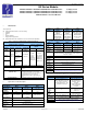

MAN0797-03-EN Specifications / Installation
__________________________________________________________________________________________________________________________________________________
9/16/2009 Page 4 of 7 ECN # 968
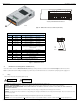
3.3.1 Primary Power Port / Grounding
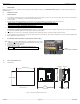
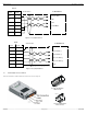
a. Port 1 (MJ1) / Port 2 (MJ2) Modular Jacks
Figure 6 – Close-up of Port 1 (MJ1) / Port 2 (MJ2) (RS-232 and RS-485)
b. Port 3 (CN1) Connector
Figure 7 – Port 3 (CN1) RS-232 / RS-485 Connector
Table 4 – Primary Power Port Pins
Signal Pin Description
V+ Input power supply voltage
V- Input power supply ground
Frame Ground
Note: Power Supply Voltage Range is from 24VDC ±
±±
±10%.
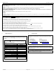
3.3.2 RS-232 Port / RS-485 Port
There are a variety of ways to connect to the RS-232 and RS-485 ports; You can use
two modular jacks (MJ1 and MJ2) or the 25-pin Dsub connector (CN1).
Table 5 – Ports and Functions (Port 1, 2, and 3)
Functions Port 1 (MJ1)
Port 2 (MJ2) Port 3 (CN1)
RS-232
RS-485
Hardware Handshaking
Programming
Ladder Function
Controlled
Modem
*
*
* Not supported by Cscape Modem Function Blocks
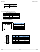
1 2 3 4 5 6 7 8
Table 6 – Port 1 (MJ1) / Port 2 (MJ2) Pins
Pin Signal
1 +SD/RD
2 -SD/RD
3 +5V
4 +5V
5 0V
6 0V
7 RXD
8 TXD
Output power supply: Max. 150mA
Table 7– Port 3 (CN1) Pins
Pin # Signal Pin # Signal
1
FG
14
QX451, 551, 651: +RTS
2
TXD
15
Not Used
3
RXD
16
Not Used
4
RTS
17
QX451, 551, 651: -RTS
5
CTS
18
-CTS
6
Not Used
19
+CTS
7
SG
20
Not Used
8
Not Used
21
Not Used
9
+5V
22
Not Used
10
0V
23
Not Used
11
Not Used
24
+RD
12
+SD
25
-RD
13
-SD
1
13
14
25