
User Manual


CH. 11 MAN0798-04-EN
August 20, 2009 Page 64 of 95 ECN # 979
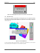
11.1.3 Resource Definitions
System Registers
System Registers (%S and %SR) are used to store general QX status information. This information
is used internally, and is also available to the operator via the System Menu, using the QX display
and keypad. The System Registers are also available for User Screens and can be accessed by
Ladder Code.
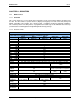
%S Registers
%S Registers are 1-bit memory locations containing system status information, which are
implemented as shown in
Table 11.2:
Table 11.2- %S Registers
Register Name Description
%S1
FST_SCN
On during the first scan after entering RUN mode
%S2
NET_OK On if CsCAN Network is functioning properly
%S3
T_10MS On for 5 mS; Off for 5 mS
%S4
T_100MS On for 50 mS; Off for 50 mS
%S5
T_SEC On for 500 mS; Off for 500 mS
%S6
IO_OK On if SmartStack I/O is configured properly
%S7
ALW_ON Always On
%S8
ALW_OFF Always Off
%S9
PAUSING_SCN
On during the last scan before Pause-N-Load
%S10
RESUMED_SCN
On during the first scan before Pause-N-Load
%S11
IO_FORCED On if one or more I/O points are currently being forced
%S12
IO_FORCING On if I/O forcing is enabled
%S13
NET_IO_OK On if Network I/O (SmartStix) is functioning properly
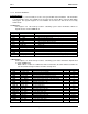
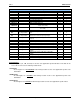
%SR Registers
%SR Registers are 16-bit memory locations, containing system status information, implemented
as shown in
Table 11.3.
Note: Where 2 %SRs are combined to make a 32-bit value, the lower numbered %SR is the
low word, while the higher numbered %SR is the high word.
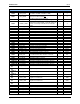
Table 11.3- %SR Registers
Register Name Description Min Max
%SR1
USER_SCR Current User Screen Number 1 1023
%SR2
ALRM_SCR Current Alarm Screen Number (0=none) 0 1023
%SR3
SYS_SCR Current System Screen Number (0=none) 0 14
%SR4
SELF_TEST Bit-Mapped Self-Test Result 0 65535
%SR5
CS_MODE Control Station Mode (0=Idle, 1=Do I/O, 2=Run) 0 2
%SR6
SCAN_RATE Average Scan Rate ( / 10) - 1000
%SR7
MIN_RATE Minimum Scan Rate ( / 10) - 1000
%SR8
MAX_RATE Maximum Scan Rate ( / 10) - 1000
%SR9-10
EDIT_BUF Data Field Edit Buffer 0 2
32
-1
%SR11-12
LADDER_SIZE Ladder Code Size 2 256K
%SR17-18
IO_SIZE I/O Configuration Table Size 16 127K
%SR19-20
NET_SIZE Network Configuration Table Size 34 1K
%SR21-22
SD_SIZE Security Data Table Size - -
%SR23
LADDER_CRC Ladder Code CRC 0 65535
%SR26
IO_CRC I/O Configuration Table CRC 0 65535
%SR27
NET_CRC Network Configuration Table CRC 0 65535
%SR28
SD_CRC Security Data Table CRC 0 65535
%SR29
NET_ID This Station’s Primary Network ID (CsCAN) 1 253