
User Manual


PAGE 32 15 MAR 2003 CH.2
MAN0305-04
a. Setup
Setup the modems to match the default serial port characteristics of the MiniOCS / MiniRCS.
9600 baud
8 data bits
No parity
1 stop bit
disable error checking
disable compression
b. Cable Wiring
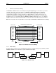
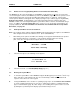
Figure 2.20 – Modem Wiring
Note: If the modem has a DB25 connector, a 9-to-25-pin adapter may need to be supplied.
The grayed connections are used only if hardware handshaking between the controller and modem
is required.
The wire type used in not overly critical except where the length of the cable must be between 30 and 50
feet (10 to 15 meters). In all cases, the cable must be shielded multi-conductor with conductors of at
least 20 gauge. The length of the cable must be as short as possible, and in no case, longer than 50 feet
(15 meters).
The modem must be located as close as possible to the OCS, preferably less than one meter. However,
EIA-232 specifications allow for cable runs up to 50 feet (15 meters). If cable lengths longer than 30 feet
(10 meters) are required, a special low capacitance cable must be used.
Warning: Damage can result if the CD and RI lines are connected to each other or to any other signal
on the connector or through the cable to the other unit.
Warning: To connect a modem to the MiniOCS / MiniRCS the controller to modem cable must be
constructed or purchased. Using a Null Modem cable can cause damage to the MiniOCS / MiniRCS,
modem or both.
DCD
RXD
TXD
DTR
GND
DSR
RTS
CTS
RI
9-PIN 25-PIN
MODEM OCS
N/C
N/C
N/C
N/C
DCD
RXD
TXD
DTR
GND
DSR
RTS
CTS
RI