
Manual


CH.9 MAN0924-01-EN
February 8, 2010 Page 44 of 124 # 1018
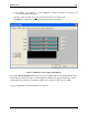
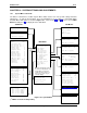
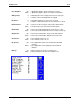
Figure 9.7: I/O Map & Module Setup Tabs
a. I/O Map Tab
The I/O Map describes the I/O registers assigned to a specific I/O module. Although there are no user-
defined parameters, the I/O Map can be viewed after
the SmartStack module is configured to review the
registers.
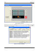
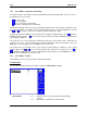
• Model number provides the part number.
• Description Describes the number of input and output channels and other key
Characteristics of the module.
• Type: Displays the register types assigned to the module.
• Starting Location: Denotes the starting location of the register type.
• Ending Location: Denotes the ending location of the register type.
• Number: Indicates the number of a particular register type.
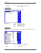
Note: Do not
confuse the described number of input and output channels with the numbers found in the
Type column (i.e., %I and %Q). The numbers do not
necessarily match.
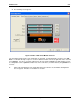
b. Module Setup
Module Setup for the I/O Selected in the above example (DIQ611) shows the output state on the
controller.