
Manual


MAN0453-04 10 NOV 2006 PAGE 3
DAC106
Information is subject to change without notice. SmartStack is a trademark of Horner APG, LLC.
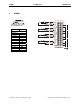
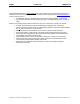
3 INTERNAL CIRCUIT SCHEMATIC
Specification for transient voltage suppressors (transorbs) used on output circuitry is 15 V, 300 W.
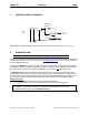
4 CONFIGURATION
Note: The status of the I/O can be monitored in Cscape Software.
Preliminary configuration procedures that apply to SmartStack™ Modules are contained in the hardware
manual of the controller you are using. Refer to the Additional References section in this data sheet for a
listing of hardware manuals.
Selecting the I/O Map tab provides information about the I/O registers, which are assigned to a specific
SmartStack™ Module and where the module is located in the point map. The I/O Map is determined by
the model number and location within the SmartStack™. The I/O Map is not
edited by the user.
The Module Setup is used in applications where it is necessary to change the default values of the
outputs when the controller (e.g., OCS100) enters idle/stop mode. The default sets the output values to
zero when the controller enters idle/stop mode. By selecting the Module Setup tab, each output can be
set to a specific value or hold the last value. Generally, most applications use the default settings.
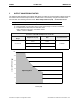
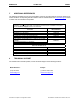
Module Setup Tab
a) Output range for each channel may be selected independently.
b) Filter Constant sets the level of digital filtering according to the following chart.
Warning: The default sets the output values to zero when the controller enters idle/stop mode.
To avoid injury of personnel or damages to equipment, exercise extreme caution when
changing the default setting using the Module Setup tab.
I/O Connector
From
Controller
1+
1-
+
-
SmartStack
Analog Out
Field
Side