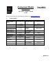
Analog Input Module HE559ADC970 12 Input Channels ±5V / ±10V / 4-20mA / ±20mA SmartStix CsCAN Refer to SmartStix Analog Programming Guide (MAN0703) at www.HornerOCS.com. 1 SPECIFICATIONS ANALOG IN Number of input points Input Ranges Resolution Accuracy, 25°C Input Impedance Register Value for Nominal Full Scale Conversion Time GENERAL Required Power (Steady State) Required Power (Inrush) 12 ±5, ±10V DC 4-20, ±20mA DC 14 bits 0.
PAGE 2 20 NOV 2003 ADC970 Vibration Occasional Vibration Frequency 10 ≤ f < 57 Hz 57 ≤ f ≤ 150 Hz Acceleration Amplitude - 0.075 mm 9.8 m/s 2 {1G} - Sweep Count 10 times in each direction for X,Y,Z Continuous Vibration Frequency Acceleration Amplitude 10 ≤ f < 57 Hz - 0.035 mm 57≤ f ≤ 150 Hz 4.9 m/s 2 {0.5G} - 10 times in each direction for X,Y,Z Shocks Maximum shock acceleration 147 m/s 2 {15G} Duration Time Pulse Wave Sweep Count 11 ms.
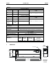
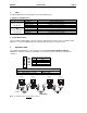
ADC970 3 20 NOV 2003 Page 3 WIRING FG 24+ * 24C ** FT NC NC +/- 10V I2i I4v +/- 10V I6v +/- 10V I6i I7i C I10i +/20mA +/20mA I12v I12i C I5i I7v I10v +/20mA I5v C I8v I8i +/20mA C I3i +/- 10V +/20mA I1v I3v I4i C +/20mA NC I1i +/- 10V +/- 10V FT I9v I9i C 2 4 6 8 10 12 14 16 18 20 22 24 26 28 30 32 34 36 38 ADC970 FG FT NC NC I2v I2i I4v I4i C I6v I6i I8v I8i C I10v I10i I12v I12i C 1 3 5 7 9 11 13 15 17 19 21 23 25 27 29 31 33 35 37 ADC970 24+ * 24C ** FT NC I1v I
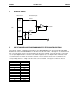
PAGE 4 4 20 NOV 2003 ADC970 INTERNAL WIRING I/O Connector SmartStack Inputs 700KΩ Voltage Input + _ Field Side To Controller 300KΩ Current Input 6V 150Ω Isolated Common 5 INPUT MODE AND PROGRAMMABLE FILTER CONFIGURATION The network supplies configuration information to the HE550ADC970 in the Consumed Directed Digital Data Words sent to the HE550ADC970. In the first word, the low 12 bits, 1 through 12, are channel mode bits. A low mode bit selects ±10V and a high mode bit selects ±20mA.
ADC970 20 NOV 2003 Page 5 Each analog input on the HE550ADC970 has a single pole 345Hz (461uS) cutoff high frequency noise filter. In addition a second digital filter may be specified in the first configuration word with the following time constants. Bit 14 0 0 1 1 0 0 1 1 15 0 0 0 0 1 1 1 1 13 0 1 0 1 0 1 0 1 Time Constant 10 milliseconds (Nominal hardware scan rate) 15 milliseconds 35 milliseconds 75 milliseconds 155 milliseconds 315 milliseconds 635 milliseconds 1.
PAGE 6 20 NOV 2003 ADC970 Conversion of Real-World Inputs into Register Values Input Data Out Conversion Factor mA or Volts > +5.11 32767 +5.00 32000 ±5.00 V 0.00 0 0.00015625 -5.00 -32000 < -5.11 -32768 > +10.23 32767 +10.00 32000 ±10.00 V 0.0003125 0.00 0 -10.00 -32000 < -10.23 -32768 < +20.37 32767 +20.00 32000 4.20 mA 0.0005 +4.00 0 -12.00 -32000 > -12.38 -32768 > +20.47 32767 +20.00 32000 ±20.00 mA 0 0 0.0006250 -20.00 -32000 < -20.
ADC970 20 NOV 2003 Page 7
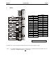
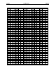
PAGE 8 Dec 1 2 3 4 5 6 7 8 9 10 11 12 13 14 15 16 17 18 19 20 21 22 23 24 25 26 27 28 29 30 31 32 33 34 35 36 37 38 39 40 41 42 43 44 45 46 47 48 49 50 51 52 53 20 NOV 2003 Hex HI LO 0 0 0 0 0 0 0 0 0 0 0 0 0 0 0 1 1 1 1 1 1 1 1 1 1 1 1 1 1 1 1 2 2 2 2 2 2 2 2 2 2 2 2 2 2 2 2 3 3 3 3 3 3 1 2 3 4 5 6 7 8 9 A B C D E F 0 1 2 3 4 5 6 7 8 9 A B C D E F 0 1 2 3 4 5 6 7 8 9 A B C D E F 0 1 2 3 4 5 Dec 54 55 56 57 58 59 60 61 62 63 64 65 66 67 68 69 70 71 72 73 74 75 76 77 78 79 80 81 82 83 84 85 86 87 88 89
ADC970 8 20 NOV 2003 Page 9 LEDS SmartStix I/O Modules provide diagnostic and status LED indicators. a.
PAGE 10 20 NOV 2003 ADC970 10 INSTALLATION / SAFETY a. b. c. All applicable codes and standards need to be followed in the installation of this product. For I/O wiring (discrete), use the following wire type or equivalent: Belden 8441 or equivalent. For detailed installation information, refer to Chapter Two in the Control Station Hardware Manual (MAN0227). A handy checklist is provided that covers panel box layout requirements and minimum clearances. Warning: Consult user documentation.