
User guide


PAGE 4 20 NOV 2003 ADC970
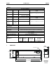
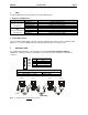
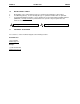
4 INTERNAL WIRING
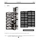
5 INPUT MODE AND PROGRAMMABLE FILTER CONFIGURATION
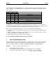
The network supplies configuration information to the HE550ADC970 in the Consumed Directed Digital
Data Words sent to the HE550ADC970. In the first word, the low 12 bits, 1 through 12, are channel mode
bits. A low mode bit selects ±10V and a high mode bit selects ±20mA. The next three bits, 13 through
15, are input digital filter time constant codes and the high bit, 16, is an adaptive filter enable bit. In the
second word, the low 12 bits are channel scale bits. A low scale bit selects ±10V or ±20mA for the
corresponding channel. A high scale bit selects ±5V or 4-20mA. The upper four bits are unused.
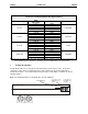
Bit Channel
1 AI1
2 AI2
3 AI3
4 AI4
5 AI5
6 AI6
7 AI7
8 AI8
9 AI9
10 AI10
11 AI11
12 AI12
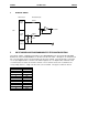
I/O Connector
To
Controller
SmartStack Inputs
Field
Side
Voltage
Input
Current
Input
Isolated
Common
700KΩ
300KΩ
+
_
150Ω
6V