
Manual


MAN0429-03 03 JUL 2002 PAGE 3
2.2.2 CAN / DeviceNet Network Port and Wiring
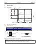
a. Network Connector
Table 3 – CAN Port Pins
Pin Signal Description
1 V- Power -
2 CN_L Signal -
3 SHLD Shield
4 CN_H Signal +
5 V+ Power +
Figure 4– Network Connector Figure 5– As viewed at the OCS
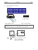
b. Grounding
Figure 6– Grounding Method
(OCS shown in this example.)
V+
CN_H
SHLD
CN_L
V-
1 2 3 4 5
V-
CN_L
SHLD
CN_H
V+
1 2 3 4 5
Warning: To provide maximum noise immunity and to ensure minimum EMI radiation, the V-
signal (DC power return) need to be connected to earth ground at the power supply. The user must
ensure that the power supply selected is compatible with this method of grounding.
DC Power
Supply
+ -
OCS
+ -
Frame
(Earth)
Ground
Connect DC V- to earth ground at the power supply.