
Manual


MAN0947-01-EN Specifications / Installation
1/6/2011 Page 1 of 3
1 Specifications
Specifications
Digital DC Inputs
Model 3
Model 4
Digital DC Outputs
Model 3
Model 4
Inputs per Module
12 including 4
configurable HSC inputs
24 including 4
configurable HSC inputs
Outputs per Module
12 including 2 configurable
PWM outputs
16 including 2 configurable
PWM outputs
Commons per Module
1
Commons per Module
1
Input Voltage Range
12 VDC / 24 VDC
Output Type
Sourcing / 10 K Pull-Down
Absolute Max. Voltage
35 VDC Max.
Absolute Max. Voltage
28 VDC Max.
Input Impedance
10 kΩ
Output Protection
Short Circuit
Input Current
Positive Logic
Negative Logic
Max. Output Current
0.5 A per point, 4A total (continuous)
Upper Threshold
0.8 mA
-1.6 mA
Min./Max. Output
Supply Voltage
10 VDC (min), 30 VDC (max)
Lower Threshold
0.3 mA
-2.1 mA
Max. Voltage Drop at
Rated Current
0.25 VDC
Max Upper Threshold
8 VDC
Max. Inrush Current
650 mA per channel
Min Lower Threshold
3 VDC
Min. Load
None
OFF to ON Response
1 ms
OFF to ON Response
1 ms
ON to OFF Response
1 ms
ON to OFF Response
1 ms
HSC Max. Switching
Rate
10 kHz Totalizer/Pulse,Edges
5 kHz Frequency/Pulse,Width
2.5 kHz Quadrature
Output Characteristics
Current Sourcing (Pos logic)
Analog Inputs, Medium Resolution
Model 3 & 4
Analog Inputs, Medium Resolution
Model 3 & 4
Number of Channels
2
Nominal Resolution
12-bits
Input Ranges
0-10VDC, 0-20mA, 4-20mA
%AI full-scale reading
32,000 counts
Safe Input Voltage Range
-0.5V to +12VDC
Conversion Speed
All channels converted every ladder scan
Max over-current
35mA
Max. Error at 25°C (excluding zero)
Current Mode: 1.00%
Voltage Mode: 0.50%
Current Mode: 100 Ω
Input Impedence
(Clamped at -0.5 to +12Vdc)
Voltage Mode: 500 kΩ
Filtering
160Hz hash (noise) filter
1-128 scan digital running average filter
2 Wiring and Jumpers
XL Series Built-in I/O – Model 3 & Model 4 I/O
Model 3: 12 DC Inputs, 12 DC Outputs, 2 Analog Inputs
Model 4: 24 DC Inputs, 16 DC Outputs, 2 Analog Inputs
for XLe, XLt, XL6 (all models) and XL10e
Wiring Specifications
For I/O wiring (discrete), use the
following wire type or equivalent: Belden
9918, 18 AWG (0.8 mm
2
) or larger.
For shielded Analog I/O wiring, use the
following wire type or equivalent: Belden
8441, 18 AWG (0.8 mm
2
) or larger.
For CAN wiring, use the following wire
type or equivalent: Belden 3084, 24
AWG (0.2 mm
2
) or larger.
Use copper conductors in field wiring
only, 60/75° C
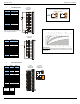
Location of I/O jumpers
(JP1 & JP3) and
wiring connectors
(J1, J2, J3 & J4) with back
cover removed.
Note: The Cscape Module Setup configuration must match the
selected I/O (JP) jumper settings.
Note: When using JP3 (A1-A2), each channel can be
independently configured.
Jumper Setting Details
20mA 10VDC
JP3
CURRENT OR VOLTAGE INPUTS
001XLE043-R1
A1
A2
A1
A2
11 22
33 44
Negative Logic
Positive Logic
JP1 Digital DC Inputs
Default
JP3 Analog Inputs